What Will I Learn?
- You will learn how to control a solenoid lock using an arduino board and relay.
- You will learn the working principle of how solenoid lock works.
- You will learn how digital input and output works and be able to program the arduino board.
Requirements
Hardware
- Arduino Uno

- Solenoid lock (12-24 vdc)

- Relay

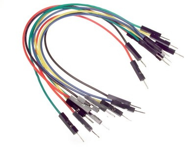
- Jumper wires

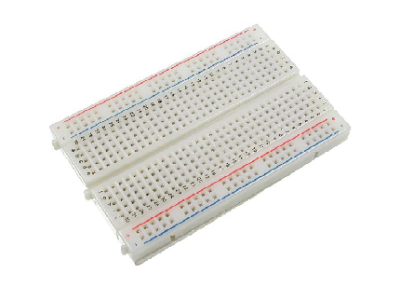
- Breadboard

- Computer

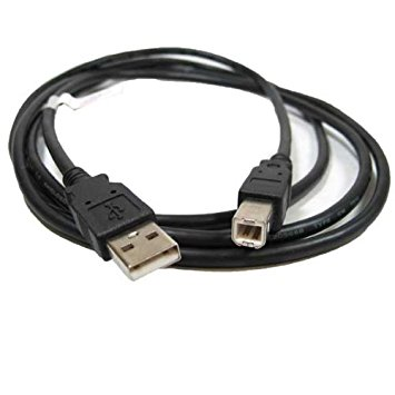
- USB type A to B cable

Software
- Arduino Software / Arduino IDE
Knowledge
- Basic electronics and programming knowledge
Difficulty
- Basic
Project description
In this project we will be using an arduino uno board to control the solenoid lock. This will help you understand how the solenoid works and how to control it using the arduino. Since the solenoid locks require higher current than the arduino can provide, it is necessary to use an alternative power source for the solenoid and the relay will be driving it.
Component description
Arduino uno - is a type of arduino board that is used regularly by specialist and hobbyist because it is the most robust of the bunch. It is packed with a microcontroller board that is based on ATMega328P with 14 advanced I/O pins (6 are PWM outputs), 6 analog inputs, 16 Mhz quartz crystal, a power jack, a USB port, an ICSP header and a reset button.
Solenoid lock - are electromagnetic locks, they are made of a big coil of copper wire with an armature (a slug of metal) in the middle. When the coil is energized, the slug is pulled into the center of the coil. Making this solenoid able to pull from one end.
Relay - is a switch that is electronically operated, they are used where it is necessary to control a circuit by a separate low-power signal, or where several circuits must be controlled by one signal.
Tutorial Contents
Step 1: Gather parts
- You can buy the following in your nearest electronic shop or order it up online. This components are common and would be easy to find.

Step 2: Construct the circuit
Connecting the Sources
- Connect the 5V pin of the arduino board into the top/bottom row of the breadboard. The connections here are connected horizontally so it is ideal to place the sources in this place.
- Connect the GND pin of the arduino board into the top/bottom row of the breadboard but make sure not to short them out.

Connect the relay
- Connect the positive terminal of the relay into the voltage source in the breadboard (+).
- Connect the negative terminal of the relay into the ground in the breadboard (-).
- Connect the data terminal of the relay into pin number 3 of the arduino board.

Connect the solenoid lock
- Connect the negative terminal of the solenoid lock into the normally open contact of the relay.
- Connect the -Ve terminal of the relay to the ground in the breadboard.

Connect the battery
- Connect the two 9 volts battery in series to supply enough current to the solenoid lock.
- Connect the positive terminal of the battery to the positive terminal of the relay.
- Connect the negative terminal of the battery to the common ground.

Step 3: Programming
- Connect the arduino uno to the computer using the usb type a to b cable.

- After the connection has been established, open the arduino IDE and go to Tools > Board: > Arduino/Genuino Uno.

- Copy the code below and paste it into your sketch in the arduino IDE.
#define solenoidpin  3    //defines solenoid @pin 3

void setup() {
  pinMode(solenoidpin, OUTPUT); //sets solenoid as Output
}

void loop() {
  digitalWrite(solenoidpin, HIGH);  //sets the solenoid into HIGH state
  delay(2000);            //duration 2 seconds
  digitalWrite(solenoidpin, LOW); //sets the solenoid into LOW state
  delay(2000);            //duration 2 seconds
}
This is a very simple code for the solenoid, this is coded this way so that you can see how the solenoid lock is controlled. First code block defines the solenoid signal terminal at pin number 3, the next code block sets the solenoid lock as the output. In the loop block it sets the solenoid lock into a HIGH state where it will activate its lock for 2 seconds and then after 2 seconds have passed it will transition it into a LOW state where the lock is deactivated for 2 seconds.
- After typing the codes into the sketch, click the Verify button to save and compile the sketch. This will also check for any errors in the program.

- If no errors where found, click the Upload button to start burning the program into the arduino uno board.

Step 4: Testing
- After the programming is complete, the solenoid lock should be working. It will start at a HIGH state for 2 seconds and then switches to a LOW state where the lock would be deactivated for 2 seconds.
- If nothing is working, redo the previous steps carefully. You may have missed something.
Curriculum
Check out my other Arduino tutorials below:
- Arduino 101: Using 2 ultrasonic sensors and servo motor
- Arduino 101: Automated parking gate circuit using ultrasonic and servo motor
- Arduino 101: Motion activated Servo motor with Arduino
- Arduino 101: PIR based burglar alarm with Piezoelectric buzzer and Arduino
Posted on Utopian.io - Rewarding Open Source Contributors
Thank you for the contribution. It has been approved.
You can contact us on Discord.
[utopian-moderator]
Hey @vladimir-simovic, I just gave you a tip for your hard work on moderation. Upvote this comment to support the utopian moderators and increase your future rewards!
Thank you @vladimir-simovic
Good work. Keep it up.
Thanks @labwork. I will keep it up for you xD
Hey @ted7 I am @utopian-io. I have just upvoted you!
Achievements
Suggestions
Get Noticed!
Community-Driven Witness!
I am the first and only Steem Community-Driven Witness. Participate on Discord. Lets GROW TOGETHER!
Up-vote this comment to grow my power and help Open Source contributions like this one. Want to chat? Join me on Discord https://discord.gg/Pc8HG9x