Introduction
Hello dear Makers! Here, in this instructable we do not use text to code, but visual objects instead when it comes programming arduino, build programs visually with nodes, A node is a block that represents physical device like a sensor, motor, or relay, or some operation such as addition, comparison, or text concatenation, that will use to define a sketch and components for microcontrollers.

What Will I Learn?
In this tutorial, you will learn the following
- how to use nodes visual programming to run text lcd
- how to display text on lcd 16X2 with i2c breakout
Requirements
For this part, you will need the following arduino components
HARDWARE
- Text LCD 16X2 with i2c breakout
- Arduino uno/nano/mega board
- type b usb cable/ for data transfer between arduino and you pc
- PC
SOFTWARE
We will going to use visual programming using XOD application, here is a brief info about the software, on installing XOD you use the XOD integrated development environment (IDE for short), which comes in two flavors: browser-based and desktop version but to upload the the sketch dorectly to the uno its better to download the software. It works on Windows, macOS, and Linux. Find a distribution package for your system on https://xod.io/

Difficulty
Either choose between the following options:
- Basic
Tutorial Contents
Experimental Procedures
I have downloaded it already on my pc, so lets start working on the code, once you have open the software there a lot of guide there on how its work, so lets start a new project on how to program the text lcd i2c using nodes.
- STEP 1: set up the lcd node from the IDE.
double click on the nodes table the search bar will appear and search for the word LCD select the version of the lcd that you have for this tutorial use the i2c ver.

This is the node object of the LCD, it has 4 set of inputs
- (ADDR) number
I²C address of the expander chip. - (BL) boolean
Backlight enable/disable - (L1) string
Text for the first line/row of the LCD - (L2) string
Text for the second line/row of the LCD

- STEP 2: Add constant -string by searching it on the node tables this string is a text node we will use it to add text to the LCD, These nodes contain and transmit data of type string.

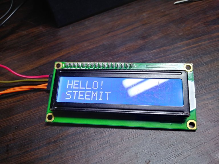
- STEP 3: Define text you want to show on the LCD by editing the VAlue of the constant -string, edit the flag sign as L1 it defines that the node is for the 1st line text of the LCD, i use the word HELLO!for the L1 and word STEEMIT to the 2nd line of the lcd


- STEP 4: connect the VAL inputs to L1 and L2 of the LCD it defines the data wires where it creates a code on its background

STEP 5: BUILD THE CIRCUIT

LCD has 4 pins (1) VCC it refers to the power signal of the LCD typically connected to 5volts, (2)GND or sometimes zero voltage, It is also the common connection of the LCD must connect to in one way or another path in order to complete the circuit. the SDA - A4 and SCL -A5.
STEP 6: connect the arduino to your PC using data cable, back on the XOD IDE then click the DEPLOY tab on the top options, verify the type of microcontroller board by tapping the board model, once scanned and no errors click the UPLOAD tab.

STEP 7: wait for deployment process it takes a moments for the first try.

- once done You should now see “HELLO! STEEMIT” displayed on the screen. Cool? Try to display your own message on the screen.

- STEP 8: Add multiple words on each lines by adding concat strings and another constant string for another set of words to be added on the LCD

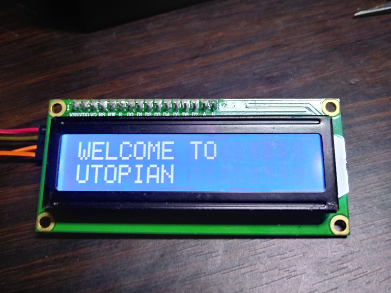
- STEP 9: The concat has 3 pins the 2 inputs and 1 output, the IN1 will be the first word on the first line and the IN2 will the 2nd word, the output should be connected to L1 input of the LCD node. change the words by editing the VALue of constant-strings. i used "WELCOME" on the first word for the first L1 and "TO" for the 2nd word. On the 2nd line L2 will be "UTOPIAN"

- You should now see “WELCOME TO UTOPIAN” displayed on the screen

- Be careful, there are many connections so chances to make a mistake are high. If you see no text, double check all connections and rotate the potentiometer at the back of the i2c breakout to adjust contrast. thank you for stopping by..
Posted on Utopian.io - Rewarding Open Source Contributors
Thank you for your contribution, yet it cannot be accepted due to the below:
Need help? Write a ticket on https://support.utopian.io.
Chat with us on Discord.
[utopian-moderator]
Hey @mcfarhat, I just gave you a tip for your hard work on moderation. Upvote this comment to support the utopian moderators and increase your future rewards!
ligwak ganern
upvoted and resteemed !! nice tutorial !! i will have a try with this software !! cheers
Nice tutorial!
thank you
Join our Discord Channel to connect with us and nominate your own or somebody else's posts in our review channel.
Help us to reward you for making it ! Join our voting trail or delegate steem power to the community account.
Your post is also presented on the community website www.steemmakers.com where you can find other selected content.
If you like our work, please consider upvoting this comment to support the growth of our community. Thank you.