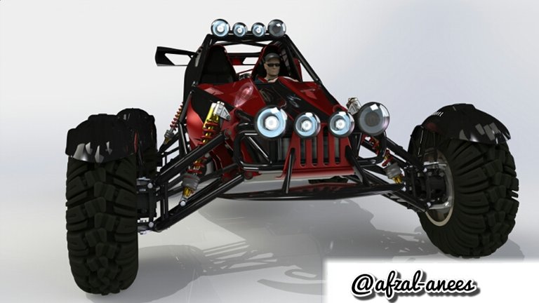
A space frame chassis is a lightweight chassis constructed from interlocking struts in a geometrical pattern this can resist high flexing loads keeping the buggy ultra light.
I have designed this roll cage on SolidWorks-2016 because it has good user interface and smooth working with high quality graphics. So let’s start....
.png)
.png)
I have chosen the easiest way to make a roll cage first according to the specifications I have drawn a 2D sketch, it’s not for off-road so I have kept the base height low then using EXTRUDE command I have made a simple shape.
.png)
.png)
Then using CHAMFER command I have trimmed the sides according to the bending of the roll cage as you can see in top-view and side-view in the above pictures.
ALL CALCULATIONS ARE DONE AS PER SPECIFICATIONS BEFORE DESIGNING.
.png)
.png)
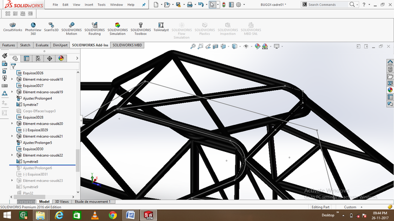
Thus it will give you the edges at which the outline of the frame can be made, So making a 3D drawing at the edges as shown in above pictures and using SWEPT BOSS command I have made a tube structure using the drawing as the path reference and the thickness is calculated according to the total weight of the buggy (including all equipments) and rider keeping it light and as much strong as it can keep safe the rider in case of accident.
.png)
Now you can see our basic outline structure is made.
.png)
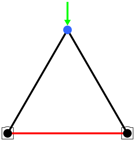
Now for strength triangular shape is made so to absorb maximum load without bending keeping the material strength in mind.

As you can see in above figure if the is applied at the blue node then the contributing rigidity of the lower red bar will neglect the bending rigidity at the blue node.
.png)
.png)
.png)
Now coming to back side making 3D drawing as per design specification and using SWEPT BOSS command taking the drawing as the path constructing to concentric circle difference between their radius is equal to the thickness of the steel pipe used and swept it along the path we get the basic structure at the back side where engine is placed.
.png)
Done the same procedure increasing the strength using triangular structure, whole procedure must be calculated so to reach the desired strength of the structure and keeping it light weighted.
.png)
.png)
Made cross shape at the roof of the roll cage thus the triangular pattern will increase the strength and added some small components like flanges and hooks to hold the engine and other parts.
.png)
Finally our space frame chassis is ready.
IF YOU LIKE THE POST PLEASE DO UP-VOTE AND FOLLOW FOR MORE TECHNICAL POSTS.
THANK YOU FOR READING, if you have any queries or want to know anything related to my field ask me in comments and I will make my next blog on it.
Great created the car. Nice to see. You are a true expert in their field.
Interesting. When designing a frame like this, does your CAD program take into account the safety of the operator?
Yes factor of safety first , lot of test is done to check the durability in designing like shear analysis, maximum load capacity test..etc etc, all calculations are some then weak points will be supported when everything is all secure then manufacturing is done.
Solid works , A very reliable software for mechanical designing. I am also a mechanical designer (AutoCAD,CAD/CAM). Which standard you are following?
Good work @afzal-anees. keep it up.
It's really amazing, you control the software very well.
May I ask you to design my new car?
Sure, anytime bro 👍 just send me specifications and basic measurements and you design will be ready to rock.
:) Thank you dear friend
@Originalworks
The @OriginalWorks bot has determined this post by @afzal-anees to be original material and upvoted(1.5%) it!
To call @OriginalWorks, simply reply to any post with @originalworks or !originalworks in your message!
Looks like an awesome project! Looking foward to see more, thanks for sharing, resteemed n' #keepsteemin :)
Thanks for appreciation brother, I am glad you liked it i will keep you all updating as we move forward in our project.
Thanks alot 😀
For who ever wants to go from beginner to expert in AI :
https://steemit.com/@neurallearner
I sure do
Come check out our series. Hope you enjoy!!