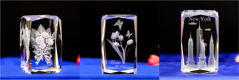
Today I will dive into physics and explain how so-called 'Bubblegrams' are made. Probably everybody has already seen some of them, but have a look at the following intriguing examples, produced by a technology called
Sub-Surface Laser Engraving (SSLE)
 Image Sources: 1, 2, 3
The basis for this technology is the same as for ordinary laser engraving on the surface of stones or glasses. Due to a very strong local temperature gradient, the material treated with the laser beam experiences thermal stress, resulting in small localized fractures.
This gives you directly perceptible breaks in stones and in engraved glasses or crystals, these micro-fractures are even more pronounced due to visible light, which scatters on them. Now how are sub-surface images made?
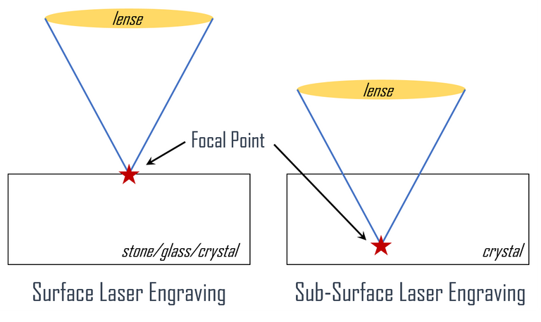
For this purpose, the lenses of the laser system are tuned to move the focal point from the surface to a spot within the material to be processed. So the difference can basically be found in a z-offset.

Illustration of the SSLE principle
selfmade
In order to be able to actually produce internal micro-fractures with lasers inside a material, it must present an essential property, which is high optical transparency. Hence only high-grade optical materials with very low dispersion are applicable. Examples are Schott BK7 or K9 borosilicate glass.
The structures to be depicted in the crystal are transferred into some kind of point cloud, which is then reproduced within the sample volume by the described 3D laser engraving technology.
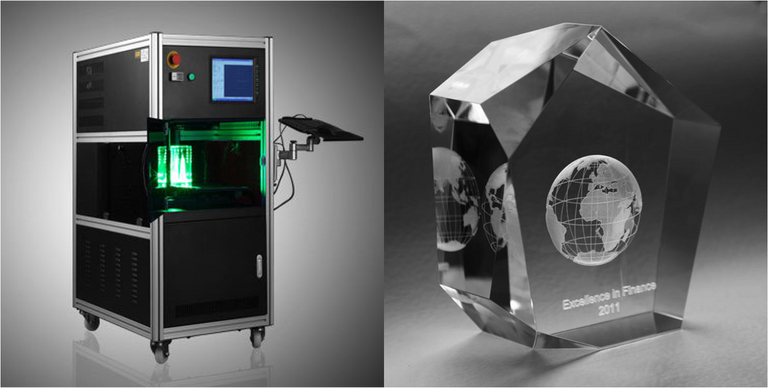
The accuracy with which these local breaks or bubbles can be generated is on the order of a few micrometers (<100μm). Also, the size of the generated inhomogeneities is typically in the region of tenths of a millimeter.
 Image Sources: 4, 5
The technology was available from the 1980-1990's on, hence is not really new, but the machines are quite costly and therefore not very common. Prices for these machines are at least in the five-digit range. The laser diode, which is the primary component and excites the pulsed solid-state laser, can easily cost a third of the machine itself and has a limited lifetime. This is one of the reasons why the SSLE technology works in a pulsed fashion.
They are often used to recreate characteristic landscapes or city features as commercial souvenirs for tourists. Meanwhile, even normal portrait photos can be converted into 3D rendered images by rather simple processing and can then be imprinted into the crystal. The presentation of scientific measurement data (e.g. MRI organscans) can also use the SSLE technology.

Image Sources: 6, 7, 8
Typical SSLE Characteristics
In order to avoid damaging the whole crystal body or to unduly stress the life of the diode and also due to the necessity of transparency of the final object only ordered point clouds and no continuous breaks are generated by a pulsed laser.
The SSLE technology do not allow for coloration. However, since the microfractures are particularly accentuated by stray light, the final object can be illuminated with colored light and thus become 'colored'.
Since the size of the points is fixed, this parameter can not be used to create some kind of gray scale. However, the dot density within a region can be used for a linear scale.
There is an upper limit to the dot density, because if the individual micro-fractures are too close to each other, so-called 'clashes' form. Clashes are larger fracture edges formed from unified microfractures.
And finally, if the dot denisty is too low, the object appears quite faint and can hardly be seen.
mountain.phil28
References:
- Bourke P. 'Presenting Scientific Visualisation Results as 3D Crystal Engravings', WASP, University of Western Australia
- 3D Laser Crystal Engraving System, Homepage
- A Wikipedia Article on Laser Engraving
- non-cited illustration of the SSLE focus principle is self-made
This is a test comment, notify @kryzsec on discord if there are any errors please.
Being A SteemStem Member
I had crystals like that, I always found that this work was very fine and precise. When I watched the video, it made me think of a 3D printer. Really very interesting ^^
Hi, this is a really good explanation. Also i want to make a comment about this, because my research is about this kind of laser systems and micromachining.
First of all, transmission of the glass too high for industrial laser systems such as Ytterbium, Erbium, Thulium etc. How can we see any ablation then? The answer is intensity on the material. The intensity depends on peak power. The peak power of your source is related to average power, repetition rate of your system. If you can get an above intensity which is higher than ablation thrashold for the material you can ablate it as you mention. Glass has a good property here which is that transmittion for below threshold intensity is almost 100%. So you can focus your beam inside the glass and you can ablate (make cracks) easily.
Have a curious day..
Nice article, thanks!
So by offsetting the Z-Axis and using not continous lines one would should be able to do it on a hobby mashine, no? If I had a laser engraver I would try it.
You need the right material so that you can efficiently focus the energy of the laser at a certain spot within the material, that shall be laser engraved. Otherwise already a quite average CO2 laser should have enough power to do the trick. - Worth a try! :)
Amazing article, I've always wanted to learn how do they do this! (not spamming, I'm actually amazed! 😄)
Hi @scienceangel!
Glad to see you around here and i'm actually really happy that you liked it. - I'm also not spamming :P :D
(PS: Upvotes for articles older than one week doesn't do a thing. Just so you know. :P )
Hahaha, I didn't even notice that your article was 3 months old!!! One more proof of how amazed I was by the content, I was focusing only on the "upvote" button :)
Hahaha, Ok i'll buy it! :P
The German version of the article got my humble upvote, it deserves it! :)
Too nice of you. 🤗
thanks for shearing.
i will definitely try it. love the concept.
thanks for sharing