This is a sequel to my previous post on Understanding the physics behind our electromagnetic world, where I discussed the
shape and direction of a magnetic field, magnetic field around a
current-carrying wire, magnetic flux and the action of some simple
electromagnetic devices and solve some calculation problems on electromagnetic
field. Today, I’ll be writing on forces on charged particles in beams and most
especially also on Hall’s effect on magnetic field.
FORCES ON CHARGED PARTICLES IN BEAMS
A television picture is produced from an electron beam controlled by magnetic fields. The beam scans across the television screen at high speed. The cathode ray oscilloscope also uses an electron beam. In fact, J.J. Thomson investigated ‘cathode rays’ in 1897 and observed how electric and magnetic fields affected them. Thomson showed that the cathode rays were tiny negatively charged particles. It was several years before they were called ‘electrons’ but Thomson is credited with their discovery.

In a beam of identical charged particles, each with a charge q coulombs and moving with an average velocity of v metres per second. The beam is moving at right angles to a uniform magnetic field of flux density B tesla. We can work out the force exerted by the field on each particle in the beam. When the length of beam in the field is l and it takes t seconds for a particle to move this distance, then:
l = vt
If the length l of the beam contains N particles, then the number of particles passing a point in the field is also N, and therefore the total charge passing through any point in the field in t seconds is Nq coulombs. Therefore the current is given by:
I = Nq / t
If we now treat the beam like a wire, then using F = IlB we get:
F = IlB
= Nq / t × vt × B
= NqvB
This is the force on a beam of N particles. Therefore the force on a single particle is given by:
F = NqvB / N
So, force on one Particle is:
F = QvB
(This time the ‘thing’ feeling the force is a moving charged particle, qv.)
We should note that an electric current in a wire is a flow of charged particles confined in the wire. A beam of charged particles is also a current – for example, a beam of electrons is a current.
EXAMPLE
Television tubes use magnetic fields to deflect the beam of electrons. Electrons are emitted from the electron gun in the tube at a speed of 3 × 10⁷ ms-1. They travel a horizontal distance of 30 cm to the screen and are deflected sideways by the magnetic field a distance of 20 cm. Calculate an approximate value for the flux density of the magnetic field required to do this. (Mass of an electron = 9.1 × 10⁻³¹ kg.)
Solution: Time taken to reach screen = 0.3 m / 3 × 10⁷ ms-1 = 1 × 10⁻⁸ s
In this time the electrons are accelerated sideways a distance s of 20 cm with an acceleration a, given by:
s = ½ at2
a = 2 × 0.2 m / (1 × 10⁻⁸ s)2 = 0.4 × 10¹⁶ ms-2
The force required is:
F = ma = (9.1 × 10-31) × (0.4 × 1016) = 3.64 × 10⁻¹⁵ N
From F = evB, the flux density is given by B = F / ev. Therefore:
B = 3.64 × 10⁻¹⁵ / (1.6 × 10-19) × (3 × 107) = 7.6 × 10⁻⁴ tesla.
Approximate magnetic flux density = 0.76 mT
MEASUREMENT OF e/m FOR ELECTRONS
The apparatus in the figure is called a fine beam tube, though it has a bulb rather than a tube. It includes an electron gun that fires a beam of electrons vertically into the spherical cavity of the bulb. As the drawing shows, the bulb is mounted between two coils (called Helmholtz coils). The coils produce a uniform magnetic field that is horizontal and at right angles to the path of the electron beam.
When the electrons emerge from the electron gun, the magnetic force is at right angles to both their direction of travel and the direction of the magnetic field. With the directions as shown, the force is towards the centre of the tube. As the electron beam turns, its direction of travel is always perpendicular to the field and the force is always directed towards the centre of the tube. This results in the electrons moving in a circular path, with the magnetic force providing the centripetal force. So, using the equation F = QvB, (in this case Q is the charge on the electron for which we use the symbol 'e'):
evB = mv2 / r
where r is the radius of the circular path.
The electron gun provides us with more information about the energy of the electrons
eV = ½ mv2
Apart from e, m and v, all the other quantities in these two equations, that is B, r and V, can be measured by experiment.
The two equations can be rearranged to give the velocity v and the ratio e/m:
V = 2V / Br
and: e / m = 2V / (Br)2
e/m for electrons is 1.76 × 10¹¹ C kg -1. With accelerating voltages of about 100 to 200 V, the velocity of the electrons is about 107 ms-1 . The apparatus described above gives results similar to these, using very ordinary laboratory equipment to make measurements. An ammeter and top-pan balance are needed to measure B, a voltmeter to measure the accelerating voltage V and a ruler to measure radius r of the beam.

Electron gun from a cathode ray tube. Roychai, Public Domain
THE HALL EFFECT
An easy way to measure magnetic fields is to use a Hall probe. The probe is based on a small integrated circuit that produces an output voltage proportional to the magnetic flux density. This ‘chip’ depends on the effect discovered in 1879 by E.H. Hall. The Hall effect allows us to gain some important information about conduction in solids, including the speed of charge carriers and the number of charge carriers per unit volume.
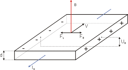
If charged particles are moving in a solid placed in a magnetic field, then the magnetic force will affect their motion. The figure below shows a slice of conducting material carrying a current. A magnetic field is applied at right angles to the direction of the current. The current shown is the conventional current. We should remember that electrons move in the opposite direction, as shown. The moving electrons are pushed by a force towards the back edge of the block. They are unable to leave the block and therefore gather at the edge.
So, in the figure showing the Hall effect, the magnetic force causes electrons to drift from the front edge towards the back edge. This makes the back edge negative and the front edge positive with a gradient in between. Like charges repel, so as the electrons, each of charge e, build up at the back, an electric field of strength E develops that opposes this sideways movement of electrons. Eventually the force from the electric field (Ee) on each electron exactly balances the magnetic force (evB).
As the charges gather at the back edge, a voltage develops across the slice. This voltage is called the Hall voltage. The Hall voltage is largest for semiconductor materials like silicon and germanium. Good conductors have much smaller Hall voltages
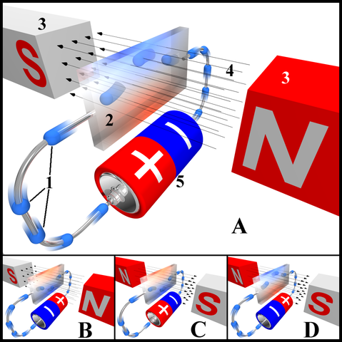
So far, we have considered the charge carriers to be electrons. In n-type semiconductors, current is certainly due to the movement of (negative) electrons. However, in p-type semiconductors, current is due to the movement of positive holes. Electrons move into holes in one direction, making the holes effectively move in the opposite direction. Therefore, the description above is correct for an n-type semiconductor, but for a p-type semiconductor, the polarity of the Hall voltage is reversed.

Hall effect. Hajder, Public Domain.
FACTORS AFFECTING THE HALL VOLTAGE
An equilibrium is quickly reached when the magnetic force on the electrons is exactly balanced by the electric force: i.e
eE = evB
But the electric field strength E can be expressed as the Hall voltage VH divided by the width d of the block of material. Therefore:
eVH / d = evB
This gives:
VH = Bvd
The velocity of the electrons can be derived from the transport equation
v = I / nAe
where n is the number of charge carriers per cubic metre. The equation for the Hall voltage now becomes:
VH = BId / nAe
This can be simplified further because A / d = t, the thickness of the block. So the final expression is:
VH = BI / nte
We can now see why semiconductor materials are used for Hall probes. The number of carriers n in a semiconductor is many magnitudes smaller than for a good conductor, but is still large enough to allow for a significant current I. A small value of n produces large Hall voltage VH. Insulators have a very low value of n, but allow very little current to flow:
For doped semiconductors, n ≈ 1022 m-3. For a typical metal, n ≈1028 m-3.

Hall effect for different directions of electric current and magnetic field. Peo, CC BY-SA 3.0
SUMMARY
In my previous post and this, I’ve been able to:
- Describe a magnetic field in terms of its shape and direction.
- Describe the magnetic field around a wire carrying a current.
- Define magnetic flux as the product of the vertical component of flux density and the area it is passing through.
- Use the unit weber (Wb) for magnetic flux.
- Describe examples of magnetic circuits and compare magnetic circuits with electric circuits.
- Explain the action of some simple electromagnetic devices using the ideas of magnetic circuits.
- Use magnetic circuits to calculate the magnetic flux density in a solenoid and around a long wire.
- Measure magnetic flux density in tesla (N A-1 m-1).
- Use the equation F = IlB to calculate the force on a wire carrying a current.
- Describe the application of magnetic forces in the moving coil d.c. motor.
- Use the equation F = qvB for the force on a moving charged particle in a uniform magnetic field.
- Describe the Hall effect and use the Hall voltage to measure magnetic flux density.
Till next time, I remain my humble self, @emperorhassy.
REFERENCES
https://www.bbc.co.uk/bitesize/guides/zyfyyrd/revision/4
http://www.kfupm.edu.sa/sites/phys102/PDF/em.pdf
http://www.citycollegiate.com/xii_chpxiv1.htm
https://www.ee.co.za/article/hall-effect-applications.html
https://www.allaboutcircuits.com/technical-articles/understanding-and-applying-the-hall-effect/
https://opentextbc.ca/physicstestbook2/chapter/the-hall-effect/
https://www.sciencedirect.com/topics/chemistry/hall-effect
https://en.wikipedia.org/wiki/Hall_effect
This post has been voted on by the SteemSTEM curation team and voting trail. It is elligible for support from @curie and @minnowbooster.
If you appreciate the work we are doing, then consider supporting our witness @stem.witness. Additional witness support to the curie witness would be appreciated as well.
For additional information please join us on the SteemSTEM discord and to get to know the rest of the community!
Thanks for having used the steemstem.io app and included @steemstem in the list of beneficiaries of this post. This granted you a stronger support from SteemSTEM.
You look to be in a very EM period at the moment ;)
Just for a while, sir.
Thanks.
Thanks for the great breakdown, will definitely have to go back through your other articles :)
You are welcome @thp88.
Thanks for coming.