This is for engineers in practice, future engineers, and anybody who wants to learn something new. I first came in contact with this topic in my 200 level class. While it was easier for folks who did technical drawing in their secondary schools, it was an uphill task for me at the initial stage. But overtime, I have come to not just like the topic, I enjoy it.
Straight to the point. What is Orthographic projection? It has to do with representing Isometric drawings which is in three - dimension (3D) to a plane figure or two - dimension (2D). Isometric drawings are of course regarded as drawings of solid shape. That means, they have length, breadth, and height. Cube, cuboid, cylinder, cone, are examples. But for two - dimensional shapes or plane figures, they only have length and height. Examples of such shapes include rectangle, triangle, square, etc.
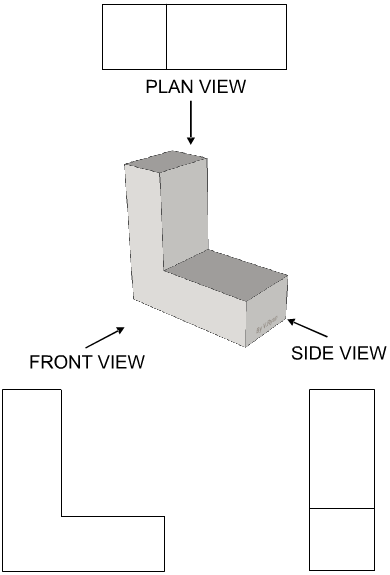
For an orthographic projection, there are four quadrants and each quadrant represent the following:
I. Plan
II. Front elevation
III. Side or end elevation
IV. The angle of elevation

Source: www.technologystudent.com
The plan shows the top view of an object to be drawn. Its like one having a view from an helicopter or when using a drone. The front elevation shows a pictorial view of the side you have chosen to be the front view. While the side view shows or depicts the side.
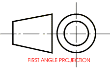
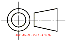
An orthographic projection can either be a first angle (mainly used in European countries) or a third angle projection (Used in USA). For the first angle, the angle is located in the cosine quadrant for those of us who understand the ACTS rule for quadrants. While the third is located where only the Sine quadrant is positive. That is another topic for another day.

Source: www.technologystudent.com

Source: www.technologystudent.com
I will be giving my examples of first and third angle projection in my next post. Have a great day ahead.
I remember this from my 100 level days... It was fun
Yeah. Especially for those who did TD in secondary school.