IMPORTANCE
These documents are the construction contract, which governs the rights, duties and liabilities of the contractor who performs the work, the organization for whom the work is executed and the engineers who design, inspect and test the work.
Engineering documents must be carefully crafted, unambiguous, prepared accurately and completely for every component of the fire alarm system to operate properly, and to avoid extra charges due lack of information during construction phase.
DOCUMENTS
NFPA 72 states clearly the minimum documentation required for a fire alarm system, however the following structure is based on my experience and exceeds minimum requirements. This list is not definitive and does not apply to every system ever designed.
System Design, see previous article FIRE ALARM SYSTEMS 3-DESIGN and [FIRE ALARM SYSTEMS 3A-PERFORMANCE BASED DESIGN] (https://steemit.com/safety/@angelparrales/fire-alarm-systems-3a-performance-based-design).
Engineering Specifications, must describe the following: definitions of roles, duties, accountability, scope of works, applicable codes, occupancy classification, type of system, location of system components, location and interfaces with ancillary devices as fire suppression or voice alarm systems. Detailed information of control panels, power supplies, annunciators, detection devices, signaling devices, modules, battery calculations, voltage drop calculations, equipment list, bill of materials.
Vendor’s Specifications, equipment cutsheets, equipment specifications, compatibility table if apply, manufacturer operation, installation and testing instructions.
System Narrative, should explain how the system will function, sequence of operation, interface with other equipments, design basis, building description, compliance with applicable codes, testing criteria and approval requirements.
System Records, includes tests acceptance reports, as-built drawings, management of change reports, reports of any inspection carried out. Owner must keep records sufficient to ensure reliable operation.
System Acceptance, testing procedures, acceptance criteria and approval requirements.
DRAWINGS
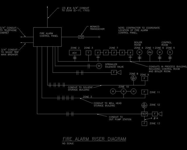
Riser Diagram Drawing,showing all devices connected to control panel circuits, addresses, room numbers and zones.

Floor Plan Drawing, Indicating every room name and intended use, ceiling height, obstructions, air supplies, complete building floor plan, control panel location; location of power sources, fire sprinklers risers, fire pumps, ancillary devices, zones if apply, smoke detectors, heat detectors, flame detectors, manual alarm stations, visual and audible alarm devices, connection and junction boxes, annunciators; wiring type, size and number of conductors as well as approximate wiring pathway.
Details Drawing, typical mounting and wiring of devices, wiring diagram of all the system.
Fire Detectors Location Drawing, precise dimensioning of fire detectors and alarm boxes, details of ceiling construction (smooth, beam, joist or slope construction) and height.
References
- NFPA 72, National Fire Alarm and Signaling Code
- clipcad.com/ccFiles/images/full/fire*rise-Full.jpg