Hi. A short post on a design that I am working for one of my printers.
It is a new heatbed assembly to replace the worn and flexible assembly. The brass nut is very used, I am waiting for replacement parts. I will try different configurations: brass nut, nylon nut and pom anti-backslash nut with different mounting points. At high speed the heatbed assembly was vibrating badly (even when the nut was new).
Since I will have to remove everything, it will be a good opportunity to upgrade and try to reduce those problematic vibrations: increase print quality.
It is a relatively straightforward design minus a "few" constraints.
I have already some parts, I want to reuse a maximum (LM8, LM8 holder, 8mm brass bushings, 2020 profile and parts)
I like this kind of challenge where you have to deal with what you have.
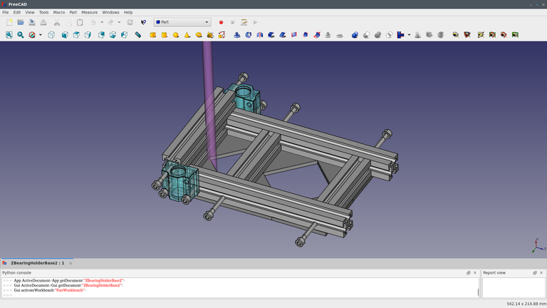
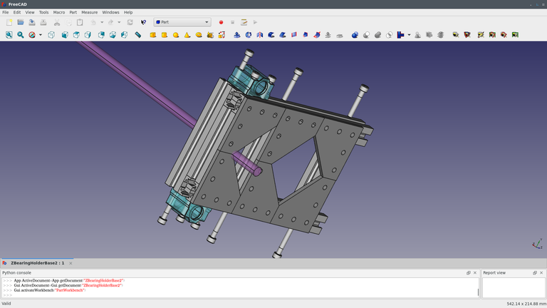
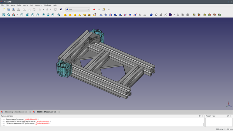
Follows a few screenshots on the mockup.


I will need to drill and tap a few holes to M5.
The 2020 profiles are a bit smaller than the existing flexible plastic crap, there is enough room to either use squares or even put directly a sheet of aluminium/steel that will help stiffen it.
The profile at the lead screw will need minor machining, I want to reduce the moment on the nut while still being able to adjust it easily on the XY plane.
It is also possible to use small corner brackets for the assembly but I find this kind of assembly a bit too light.

I have also 30mm long brass bushing, it is a good alternative I think, more surface contact on the rods and also tighter clearance than LM8. I have adjustable clearance LM8 it would be interesting to see what can be done.
Given the short length of the assembly the 2020 aluminium profile with less than 250mm, a distributed load of 2 Kg will deflects less than 0.1mm. Using this link below to compute: https://8020.net/deflection-calculator
The problem is not any more there, the bottleneck of the cantilever design is on the rods: probably I will double the number of 8mm rods because the deflection is not acceptable given a length of about 300mm, and it puts too much stress on the nut (reuse constraint otherwise I would put at least 12mm rods).
Another interesting optimization is to try to minimize the length of the rods between the supports, even reducing 50mm can help a lot on the deflection.
Happy printing