In this post I will teach you how to setup an Endbots DESC
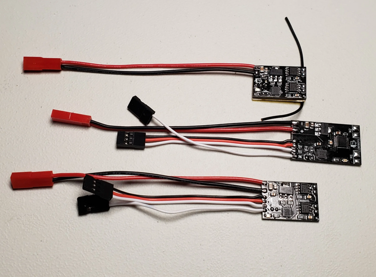
The DESC is designed to control drive motors for Fairyweight, Antweight, and Beetleweight Combat robots. It features Failsafe, Current Protection, Mixing Option, and much more…
Please read these instructions completely prior to using this product.
if you are unsure ask for help or get an expert to assist you.
Warning: This product can get hot enough to burn you. Take care when handling this product.
As we setup the DESC we are going to test it at the end of each step. This will help us diagnose any issues related to your setup as they come up instead of at the end when everything is put together.
Note: Do not solder on extra components (servos, extra esc’s) until you have tested the board according to the instructions.
Skills Needed
- Soldering (Beginner)
- Supplies Needed
- Endbots DESC (any type)
- Receiver (Standalone & Budget Only)
- Radio (Compatible with receiver used, Lemon-rx is DSM2 Compatible)
- Wire 22g-24g Silicon wire recommended
- Wire Cutters
- Wire Strippers
- Soldering Iron (with a pointed clean tip)
- Wet Sponge or Brass Mesh
- Small diameter 60/40 Leaded Solder*
*lead free can be used but it is not recommended as it is much harder to work with.
Power Requirements
Depending on which board you are setting up you will need a power source capable of supplying the correct voltage.
- DESC Lemon-RX & Standalone need at least 6.5v but no greater than 16.8v (2s to 4s lipo)
- Budget DESC needs at least 5v but no greater than 12.6v (2s to 3s lipo)
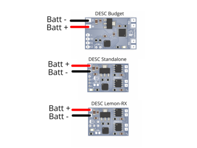
If you are using a different connector carefully replace the connector with the style you are using.
Pay careful attention to the polarity and always use a connector that can only be plugged in one way.
Plugging in a battery backwards will destroy the DESC!
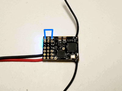
Testing the Board
- Plug in your power source. If everything is working correctly the blue led should be blinking slowly (older versions will have solid light)
- You can now unplug the DESC.
- Troubleshooting
If you plug in the battery and nothing happens, check your connections and make sure your battery is charged.
Binding Your Radio
The next step is to bind your radio to the receiver.
The all DESC are compatible with any radio that transmits one signal per wire (PCM)
PPM Only (Single Wire) receivers are not supported.
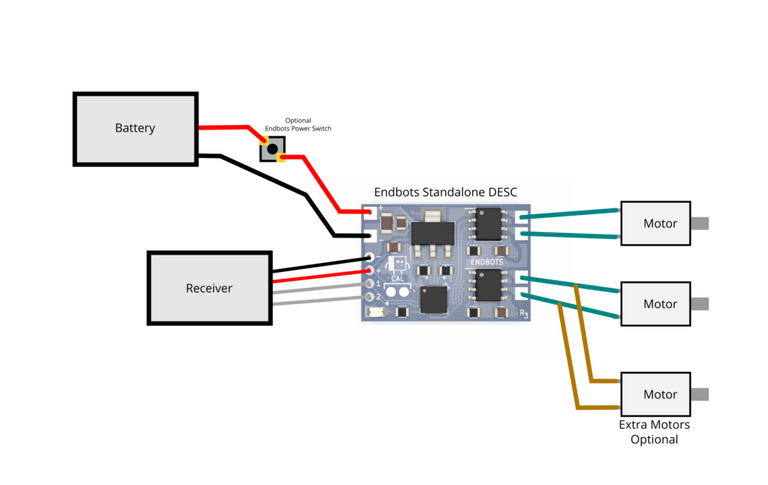
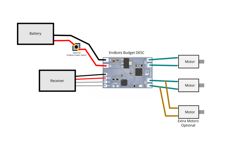
Standalone & Budget Versions
- Plug in the connectors to the radio channels you are using. Most people use aileron and elevator. Make sure the white signal wires are facing the correct direction.
- you will need to consult the receiver’s directions to see which way it is supposed to be. On the Lemon Rx the signal pin is the set furthest in on the board.
- After plugging in the signal cables plug in the bind plug into the binding slot and plug in your power source for the DESC.
Lemon-RX Version
Binding the lemon-RX DESC can be a little tricky. Thankfully it is something that you should only have to do when switching radios. You need to bridge the inside and outside bind pins as shown above and then apply power.
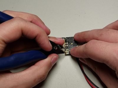
The easiest way I have found to do this is to use a pair of pliers or snips to bridge the gap.
If you have trouble holding the bridge get a helper to plug in the power source for you.
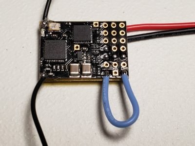
Lastly if all else fails you can solder a small bit of wire to the lemon-rx to form the bind plug.
Note: Remove wire after binding.
Note: Only solder when the power is not connected to the device.
Apply Power
Plug in your power source to the DESC.
You can let go of the bridged pins as soon as the power is applied.
If you are using the lemon-rx as a receiver the red light will be rapidly blinking. This means that it is ready to bind.
If you are using a different receiver consult the instructions
Binding using Spektrum DX6i
- Turn on the radio and select the model you wish to use in airplane mode.
- Turn off your radio.
- While holding up the switch labeled “Trainer” turn your radio back on.
- Hold the switch for 5-10 seconds then release it.
- the red light on the Lemon-rx should go solid.
- Binding using the Spektrum MLP4DSM
Binding using MLP4DSM
- push the throttle to the lowest position and push the stick in
- turn on your radio
- Hold the stick in for 5-10 seconds then release it.
- the red light on the Lemon-rx should go solid.
Notes
- For other radios the process is similar, please consult the radios instructions
- With the radio bound you can now remove power from the board and remove the bind plug.
- The lemon-rx receiver will sometimes blink red instead of solid red. This is because the board had a brown out condition for a split second (usually occurs while it is being turned on) It will not negatively affect operation.
- For versions 3 and later the DESC will blink the blue light slowly if it is not receiving a signal from the receiver. Older versions should always have a solid light under normal operation.
Soldering
Now we are finally ready to solder to the board. If you are a beginner we recommend getting someone who is experienced to help you. Soldering is easy but it does take some practice before you start making really nice connections.
Lemon-RX DESC
Standalone DESC
Budget DESC
- Prepare the wires and pads
- Cut your wires to length 3/16″ to 1/4″ oversize.
- Strip off approximately 1/8″ of the insulation from the ends of the wire using the wire strippers.
- Twist the ends of the wires, this helps prevent stray strands from causing bridging.
- Touch the soldering iron to the end of each wire and apply solder to the wire (not the iron)
- Trim the wires so only 1/16 of an inch is exposed (this is important!)
- Touch the soldering iron to each pad of the DESC and apply solder to the pad (not the iron)
- Solder wires to the motors
- Touch each motor tab with the soldering iron and apply solder to the tab (not the iron)
- You want to keep the amount of time you are touching the tab to a minimum as too much heat can damage the end of the motor especially if it is plastic.
- Touch the wire to the tab and then touch the iron to the tab and wire until it melts and then pull the iron away. This should take a second or two max.
- Repeat for the other wires.
Calibration
WARNING: Robots may make unplanned movements during this step! Please take proper precautions to ensure that the robot cannot move even if the motors or wheels turn unexpectedly.
Calibrating the DESC is a simple process.
- Turn on your radio.
- Center the trim pots on your radio.
- With the power on and the blue led solid, Bridge the pins marked “CAL” or on older versions, insert the calibration button and press it.
- The blue led should be blinking rapidly this means you are in calibration mode.
- Move each stick on the radio to the max and min travels several times
- Center the sticks.
- Bridge the pins marked “CAL” again or press the calibration button and remove it.
- The blue led should now be solid
Calibration Mode
The DESC is now calibrated.
Each time you calibrate the driving mode changes.
EXAMPLE
MIXED MODE –> ENTER CALIBRATION –> SWEEP STICKS –> CENTER STICKS –> EXIT CALIBRATION –> UNMIXED MODE
UNMIXED MODE –> ENTER CALIBRATION –> SWEEP STICKS –> CENTER STICKS –> EXIT CALIBRATION –> MIXED MODE
NOTE: Some old boards have either mixed or unmixed mode only and are not changeable.
Testing Failsafe.
Move the stick on the radio so both motors are moving
Switch off the radio
No Radio Signal (version 3.0 and later)
- If you have a version 3.0 or later the blue led on the board should start blinking slowly and the motors should stop.
- If your board is older than version 3.0 then the motors should stop and the blue led should be solid.
- If your board does not fail-safe then check your connections and try again.
Testing your robot
Now that we have the drive motors attached and radio calibrated we can test your robot.
- Place your robot on blocks so it cannot move.
- Power on your radio
- Power on your robot
- Switch calibration modes until you are in unmixed mode. (you must sweep sticks each time you enter calibration mode)
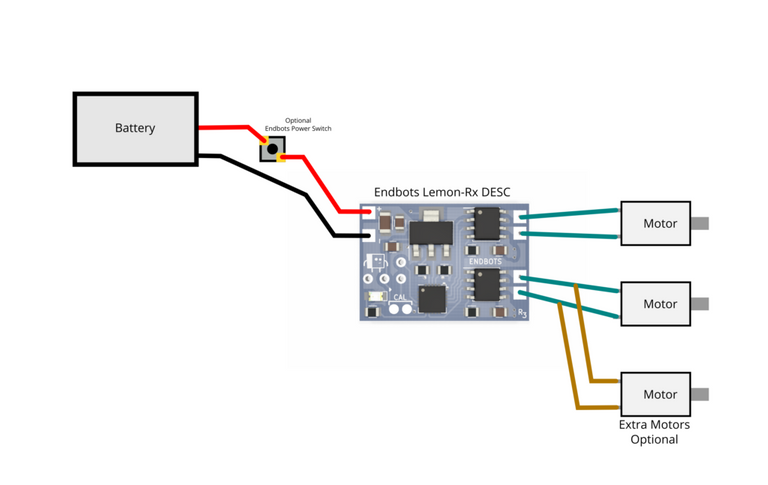
- Using the diagram below swap motor leads or channels until the two green boxes are true*
- Switch calibration modes so you are in mixed mode.
- Your wheels should now move in the correct direction.
- Power off your robot and radio.
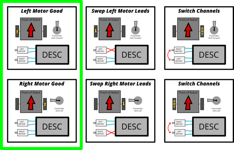
*If you are using a standalone or budget and you get stuck try swapping the channel servo plugs.
And that's it. If you have any questions comment below and I'll do what I can to answer them.
Hi! Just want to ask if this is your blog: http://learn.endbots.com/course/setting-up-a-desc/?course_type=content&course_page=3&lecture=1§ion-quiz=1
Yes but i'll be taking it down soon.
Congratulations @chaoscommander! You have completed the following achievement on the Hive blockchain and have been rewarded with new badge(s):
Your next target is to reach 100 upvotes.
You can view your badges on your board and compare yourself to others in the Ranking
If you no longer want to receive notifications, reply to this comment with the word
STOPCheck out the last post from @hivebuzz:
Support the HiveBuzz project. Vote for our proposal!