If you’ve been following my previous posts, you already know I’m working on building a remote-controlled robot. As I’ve mentioned before, this robot will move on four wheels and will have two motors—one servo motor for steering and a DC motor (6–12V) for driving the rear wheels.
![dc d.mp4_snapshot_00.05_[2025.01.20_22.0sssa2.12].jpg](https://images.hive.blog/768x0/https://files.peakd.com/file/peakd-hive/hadif66/23wC9zrwFx5P1vMYd2Bgbh9BZCdtKRnbwkzrhB54QgapMdr4zq5nLGXKBp6vS7A8ajDdW.jpg)
Anyone who’s worked with DC motors knows that their speed and direction aren’t easily adjustable without some help. That’s where a DC motor driver comes into play. Initially, I wanted to build my own motor driver using transistors or MOSFETs, but I couldn’t find the necessary components in local stores. So, I opted to purchase a motor driver module instead.
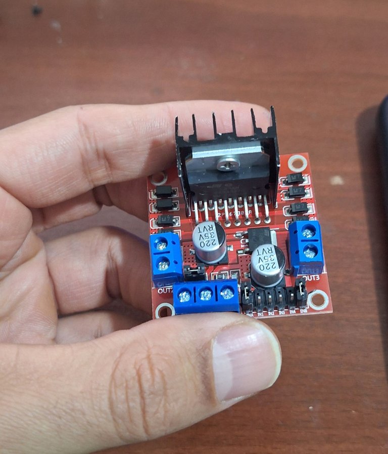
I chose the L298N motor driver for this project. Not only is it a reliable choice for my current needs, but with its dual output capability, I can also use it in future projects if I decide to control two motors simultaneously.
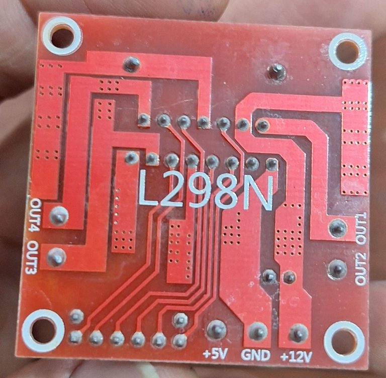
Unboxing and Setting Up the L298N Motor Driver 🔧
Once the module arrived, I wasted no time getting started. Setting it up was a bit tricky, though. After a few hours of trial and error, along with some research, I managed to figure it out.
To test the module, I designed a small project that allows me to control the speed and direction of the DC motor manually using a potentiometer. Here’s how I set it up:
Wiring Diagram and Connections ⚡
For this setup:
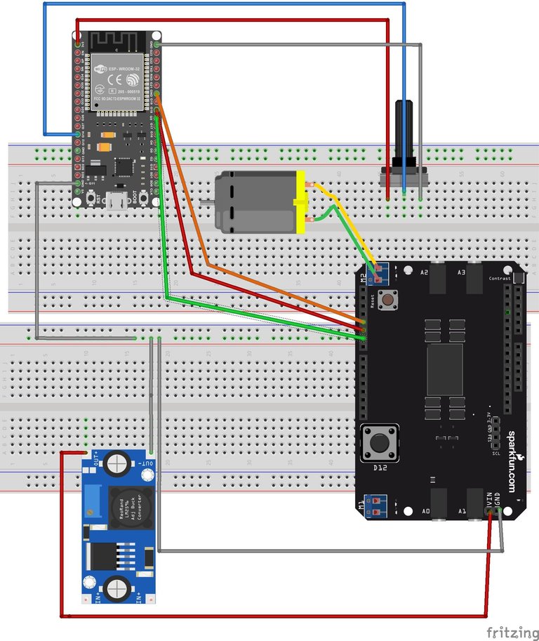
(I designed this in Fritzing, it might not be very accurae but that's all I have at the moment)
Power Supply:
I connected a 19V adapter to a DC-DC buck converter to step down the voltage. My DC motor operates at 2V, but I wanted to run it at 10V for this test. By adjusting the buck converter’s potentiometer, I set the output voltage to 10V.
Common Ground:
The ground terminal of the power supply is connected to the ground pins of the ESP32 and the L298N module. Sharing a common ground is essential for proper communication between components.
ESP32 to L298N:
Pin 12 of the ESP32 is connected to the Enable pin of the L298N.
Pin 4 is connected to IN1, and Pin 32 to IN2 of the L298N.
Using the Enable pin, I can send PWM signals to control the motor’s speed. By toggling the states of IN1 and IN2 (HIGH or LOW), I can control the motor’s rotation direction.
DC Motor:
The DC motor is connected to the L298N’s output pins.
Potentiometer to ESP32:
The left pin of the potentiometer is connected to the 3.3V pin of the ESP32.
The middle pin is connected to GPIO14.
The right pin is connected to the ground.
Powering the ESP32:
To power the ESP32, I used a separate 3.3V or 5V power source.
Testing the Setup 🛠️
With everything wired up, I wrote a program to:
- Adjust the motor’s speed using the potentiometer,
- Change the motor’s direction by toggling the IN1 and IN2 pins.
The result? It worked perfectly! The L298N performed well, and the DC motor responded accurately to the controls.
Lessons Learned and Next Steps 🎯
This milestone is a significant step forward in my robot-building journey. Every step brings its own challenges, but overcoming them is part of the fun. For now, the focus is on integrating this motor control system into the robot’s overall design and preparing for the upcoming challenges.
I almost forgot to mention—initially, the DC motor wasn’t spinning in reverse, and it took me two hours to figure out the issue. Turns out, I had connected the IN2 pin of the L298N to GPIO pin 35. The problem is that on the ESP-WROOM32, GPIO pins 34 to 39 are input-only, and I learned this the hard way. I’m sharing this with you so you don’t fall into the same trap I did.
I’ve also created a video tutorial showing how I set up and tested the L298N module. You can watch it on my YouTube channel here:
Thank you for following along! Your support means a lot to me. Please share your thoughts, and wish me luck as I tackle the next steps in this exciting project.
Your update on the remote-controlled robot project is fascinating. using a L298N motor driver module for controlling movement, along with the wiring and testing process is quite amazing. Thanks for sharing your progress update.
You are welcome, I'm glad you liked it, thanks for your support, it motivates me to go on with my goal to make better electronics and robots, one day my robot will come to life, wish me luck.
Congratulations @hadif66! You have completed the following achievement on the Hive blockchain And have been rewarded with New badge(s)
Your next target is to reach 2000 upvotes.
You can view your badges on your board and compare yourself to others in the Ranking
If you no longer want to receive notifications, reply to this comment with the word
STOP