Hello, everyone! Finally, I am able to post. After a few days of not being active due to a heavy load of school lectures and stress. I'm delighted to be back on this wonderful platform.
I'll be lecturing on the practical that my departmental mate and I did on "measuring the resistance of the armature winding using compound Excited DC Generator".

AIM
Measuring the resistance of the armature winding using compound excited Dc Generator.
OBJECTIVES
To determine the resistance value of the armature windings of a compound dc excitation Generator using Volt-ampere method.
THEORETICAL REVIEW
The measurement has to be performed in Dc condition and with steady machine, in each case, it is necessary to operate with "cold" machine I.e not working for several hours, to be sure that every part of it has achieve the Room temperature. The resistance of the armature windings can now be measured using Volt-ampere method.
COMPONENTS USED
Variable Dc output source
Ammeter (0-20A)
Voltmeter (0.5-1v)
Voltmeter (5-10v)
Compound Dc Generator -DL10240
Connecting leads
Tachometer - speed range measurement
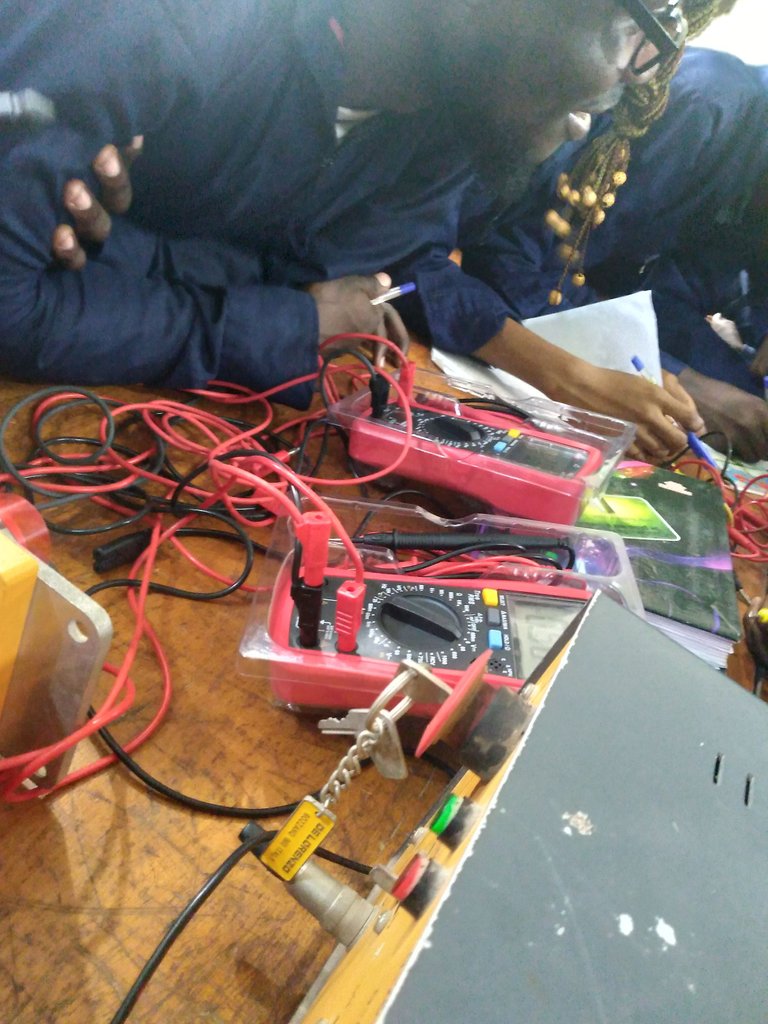
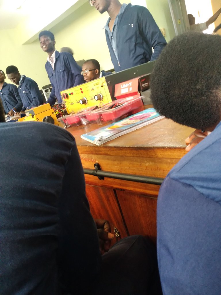
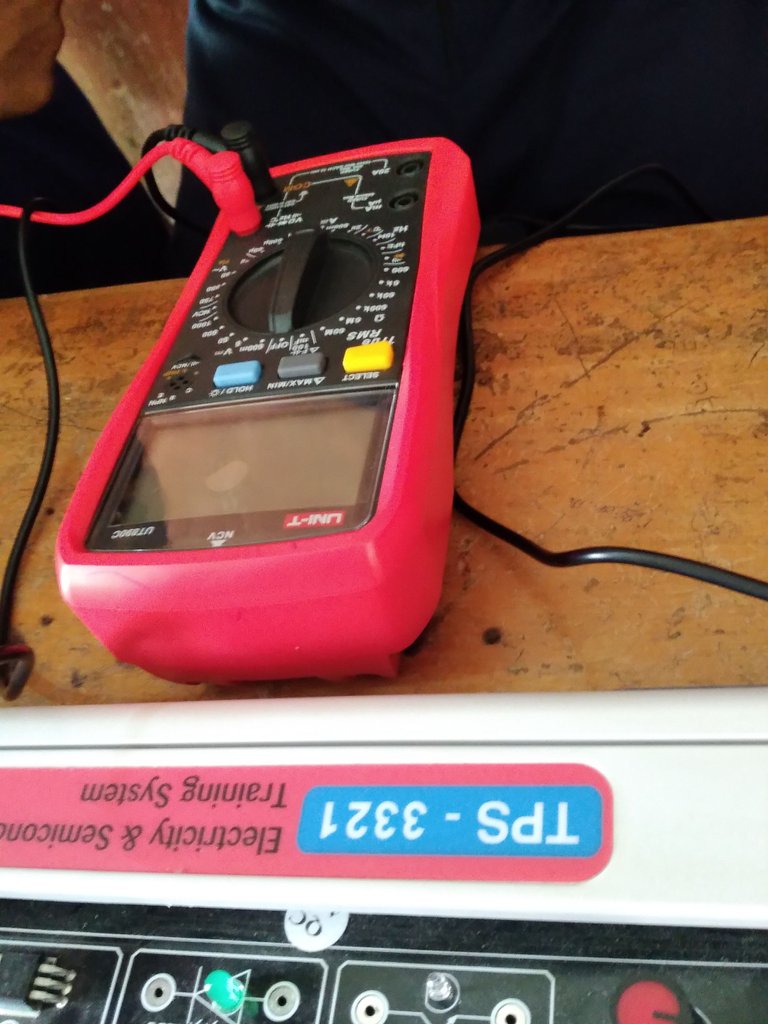
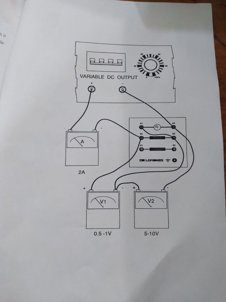
A layout of the connections circuit was Printed as Guidelines for us to Follow and the connections Goes Thus;
The positive probe of the Variable Dc output was connected to the positive probe of the Ammeter and the negative probe of the Ammeter was connected to the D1 of the compound Dc Generator and looped back to the positive probe of the first voltmeter. The negative probe of the first voltmeter is connected to D2 and looped to A1 of the compound Dc Generator. The negative probe of the Variable Dc output source is connected to A2 and looped to the negative probe of the second voltmeter and the positive looped to the negative probe of the first voltmeter.
PROCEDURES WE FOLLOWED WHILE EXECUTING THE EXPERIMENTS
STEP 1. I set up the module to a variable Dc output source.
STEP 2. I switched open and set the variac fully turned in counter clockwise direction.
STEP 3. I close the switch in variable Dc output section.
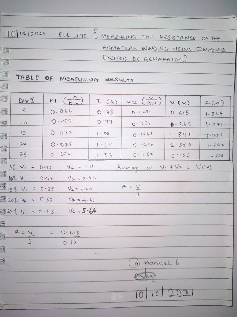
STEP 4. I rotate the variac in a given range until a current of approximately 1.5A is obtained from the Ammeter (A) and record the corresponding values of Voltage (V) from the Voltmeter.
STEP 5. I Connect to the voltmeter a pair of conductors with measuring tips and connect it between terminal D1-D2 and read the V1 indication.
STEP 6. I Connect to the voltmeter a pair of conductors with measuring tips and connect it between terminal A1-A2 and read the value of V2 as indicated.
STEP 7. I Opened the switch.
STEP 8. I recorded the readings in the Table of measurement result drawn below.
CONCLUSION
At the end of Today's class I was able to mention some Areas of Application of compound excited Dc Generator
Thanks for taking your Time Going through my Blog.
Wow, @manuel6 this is a good one and I believe you learnt quite a few things. By the way, how do you how get the armature resistance?