In my second post I shared how easy it was to recycle an old PC power supply. Just don't forget the fuses, my PS can deliver 5V @ 15A & +12V @ 16A & 18A, more than enough to damage your circuits if you don't protect them!
I designed this system using a Raspberry Pi 3 B+ before the 4's came out and briefly thought about upgrading, but the 3 isn't even working hard, so I don't see any need.

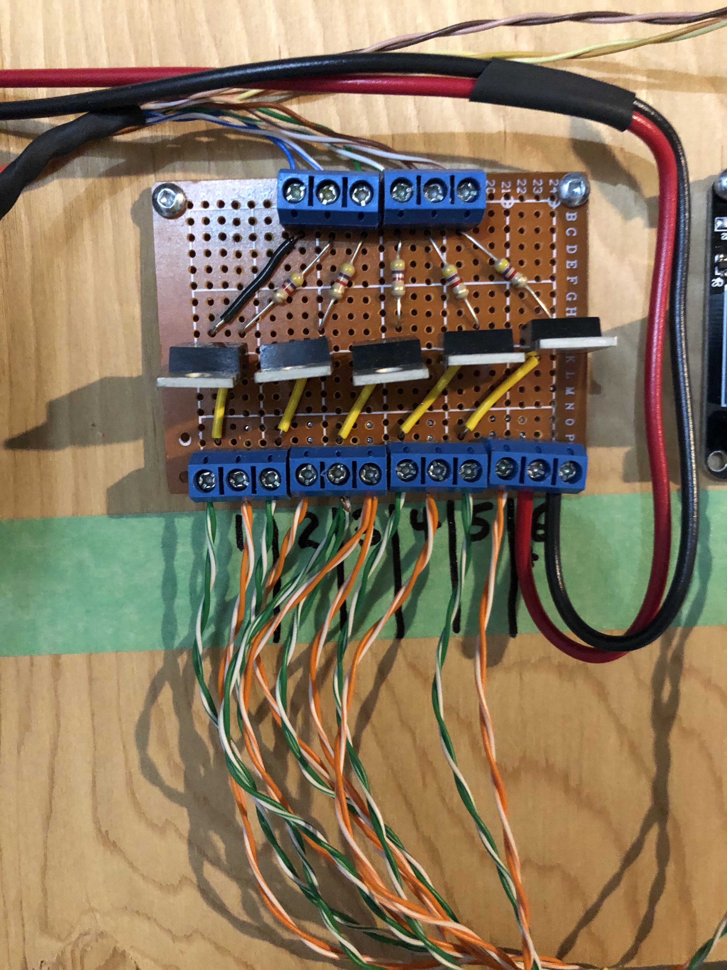
This is a close-up of my MOSFET driver used for my LED light strip. These are needed because the Pi's can only safely source ~ 16mA per pin to a max of ~51mA on the device according to the element14 notes I've read. So you need to have a device that can take a small input current (from the Pi) and control a large output current (or voltage). A transistor, MOSFET, or relay can do this for you.
I have a 3 step process when I'm prototyping.
- Design and validate the circuit on a solderless breadboard
- Solder the circuit on a basic piece of perf board as I've done here
- Learn how to make gerber files and get some proper circuit boards built!!!
*** Needless to say, so far my circuits only make it to step 2 (grin!)
I get my parts from Newark.ca, or Digi-key.ca, both have very competitive prices and great delivery. The blue terminal strips I ordered off of ebay.ca and they are great for wiring up these generic perf boards.

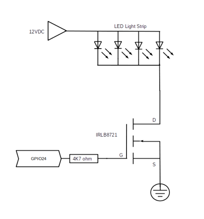
This is my first schematic made on Libre Draw and I can see I've got a lot more work to do on the MOSFET!
The LED light strip is connected to +12VDC from the power supply and when I energize the MOSFET I provide a ground or negative connection from the source to drain on the MOSFET
Here is the datasheet for the IRLB8721 and I just want to point out a few important parameters:
- Vgs(th) = Gate > Source threshold voltage of 1.35 - 2.35V. The Raspberry Pi is a 3.3V device and so you want a FET that can trigger off that low voltage, and this one does!
- Vds of 30V, so I can use this device in my garage solar system that is running at 24VDC. I'm going to experiment with PWM (Pulse Width Modulation) to run 12V LED Light Strips from 24V without having to go through a power supply. But for now, it can easily handle the 12V coming from my PC supply.
- Idrain of 44A - 62A (depending upon device temperature) so lots of capacity for my LED light strips.
- If you look at the schematic pic on page 2 of the datasheet, you'll see an internal diode connected from the Source to Drain. This reverse p-n junction diode acts as a freewheeling diode to protect the FET if you hook it up to a relay coil.
- And best of all, about $1.13CDN if you buy 10 at a time from newark.ca
It is an insulated gate, meaning that the gate lead doesn't have an electrical connection to the drain or source, and this provides a very high input impedance. Which means that it takes very little current on the gate to control the large current from the drain to source. The 4K7 (4.7kohm) resistor is to limit gate current, but to be honest, I've not sure it is necessary since the gate is insulated. Better to be safe than sorry (grin)!
I've used these MOSFET's to drive LED lights, relays and small 12V pumps for watering my garden and they work great!
Please let me know if I haven't explained this circuit enough, or properly. My 'real' job is an Electrical Apprenticeship Instructor and I do try to break things down into easy to follow steps, but this is my first foray into blogging and may still be making many assumptions on my posts?
And finally, this is my first post completely designed and deliver via my Pi400. It may be slower than my iMac, but it was a lot of fun, and exciting to learn about the capabilities of this little PC!
Thanks for viewing!
Robin
Posted with STEMGeeks
Glad to hear you like the RPi400, interesting form factor which makes it more usable.
Yes, the Pi400 is a nice form factor, and the internal heat sink does keep it running cooler, not that I am running any processor intensive software. I have a Pi 4, 8GB mounted on the back of my monitor as well and it works great, I'm thinking about moving it out to my garage, to replace a very old PC that I had been using.
Congratulations @robingreig! You have completed the following achievement on the Hive blockchain and have been rewarded with new badge(s) :
You can view your badges on your board and compare yourself to others in the Ranking
If you no longer want to receive notifications, reply to this comment with the word
STOPDo not miss the last post from @hivebuzz: