This do-it-yourself guide requires basic electronic skills like soldering, pcb masking and etching process and basic knowledge in programming with C language.Fire is classified as one of the most devastating man-made disasters. The financial and other damages caused by the fire incidents are life-threatening. Although fire authorities are always there to help in times of fire disasters, fire prevention and early detection is the best way to avoid being a victim. With these reasons, I have come up with an idea to use microcontrollers like PIC16F84A to make a reliable fire alarm system.
A Fire Alarm System is an integrated system commonly composed of electronic components which primary purpose is to detect early causes and stages of fire thru heat sensing or by smoke detection. PIC16F84A microcontroller is a CMOS Flash/EEPROM- based 8-bit microcontroller that has 18 pins. It can be used for prototyping projects and can be updated and reprogrammed without removing it from the system thru in-circuit serial programming (ICSP).
Before I start, here are the hardware and software requirements that are necessary for this guide:
Materials Needed
• PIC Flash Programmer
• 18-pin IC socket
• Printed Circuit Board (4" x 4")
• Ferric Chloride
• Mini drill
• Soldering Iron
• Soldering lead
• Power Supply Unit
• 2 x 22 pF ceramic capacitors
• 1 x 14 MHz crystal oscillator
• 1 x 5 kohm NTC thermistor
• 3 x 500 ohm resistors (1/4 W)
• 1 x 1N4148 diode
• 1 x SPDT Relay
• 2 x BC547 transistor
• 1 x tact switch for the pushbutton
• 1 x buzzer
Note: I think it is necessary to use an IC socket in making circuit prototypes rather than directly soldering the IC on the printed circuit board. For instances that the IC might get damaged, you can easily replace the IC if it is not directly soldered. For the power supply, the minimum voltage range must be greater than 5 V.
Required Softwares
• MikroC
• PICFlash
Note: The Proteus Professional is used to simulate the circuit and to make a PCB layout for the masking process. The MikroC is used to write the HEX program of the microcontroller. And the PICFlash is used to flash the HEX code into the microcontroller.
"Are you ready? Let's start!"
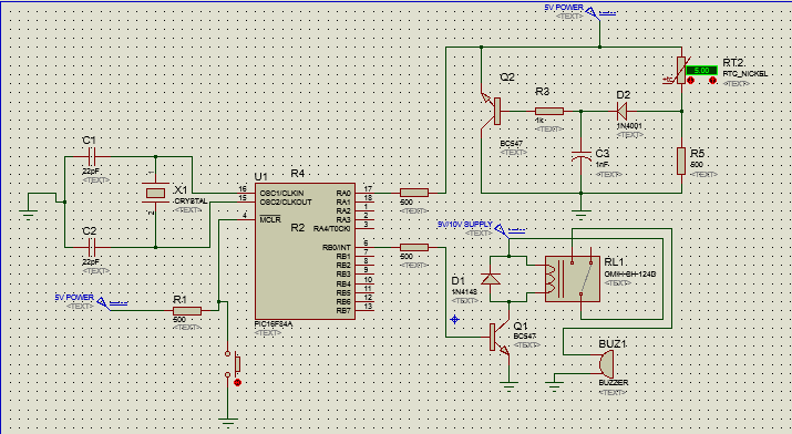
The PIC16F84A is a microcontroller. It acts as the processor of the system and it evaluates the I/O that are needed for our system. The connections of the 22pF capacitors and the crystal oscillator creates a clock circuit for the microprocessor. The pin 17 of the PIC16F84A acts an input pin for heat sensing while the pin 6 of the PIC16F84A is the output pin for our alarm. I use a NTC( Negative Temperature Coefficient) thermistor. The resistance of the NTC thermistor decreases as the applied external temperature increases. Thus, if an ample amount of heat like a fire is sensed by the thermistor, the resistance of the thermistor decreases. Therefore, on the voltage divider on the input circuit with the thermistor, the voltage across the resistors will be greater than 0 and the voltage across the thermistor will be close to zero. This can be proven by a solution of voltage divider circuits in theoretical analysis. The base of the transistor, BC547, by then will have an input that is high. So, the transistor will be ON. There is an input voltage source of 5 volts connected to the collector and it can be fed to the input pin 17 of PIC16F84A through the emitter. Once the pin 17 of the microcontroller is high, the microcontroller will set the pin 6 of the PIC16F84A high, triggering the relay where the buzzer is connected. Thus, the buzzer sounds.
The Step-by-step Procedures:
1. The Circuit Modeling Process
2. Programming the PIC16F84A
3. The PCB Masking and Assembly Process
The Circuit Modeling Process
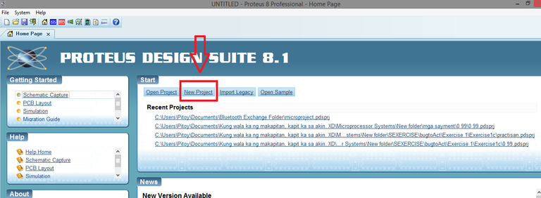
Step 1: Open Proteus 8 Professional. Make a new project and draw the circuit diagram, as shown above. Don't forget to check the radio buttons that asked to create both the schematic and PCB layout, for your convenience.
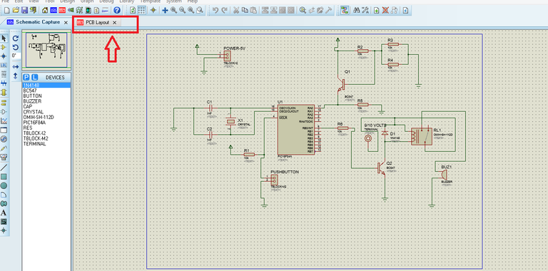
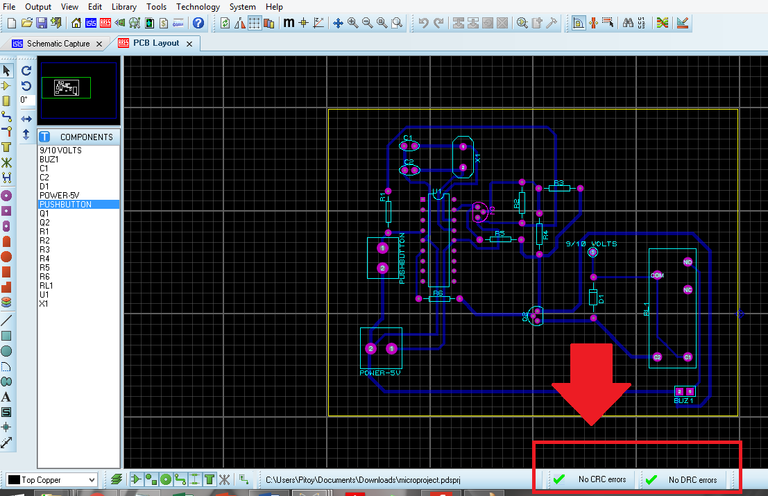
Step 2: When you are done with the schematic diagram, click on the PCB Layout and start routing the components until no CRC and DRC errors are shown on the ribbons below.
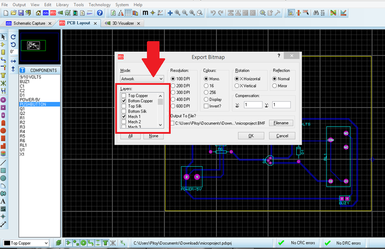
Step 3: Click on output, export it as a bitmap image. Make sure to check only the bottom copper. You will need to print that image later for the PCB masking process.
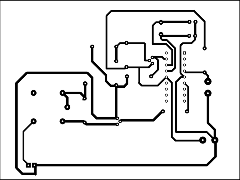
Here is the bitmap image of the circuit for the masking process:
Programming the PIC16F84A
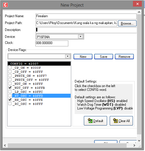
Step 1: Open MikroC and make a new project.
 And input the following codes:
The code above simply implies that when pin 17 of PIC16F84A is high, pin 6 will be high too. Their state would directly be similar. Pin 17 is set as an input pin while pin 6 is set as an output pin.
Step 2: After saving the project, connect your PIC16F84A to your PIC Flash programmer in this way.
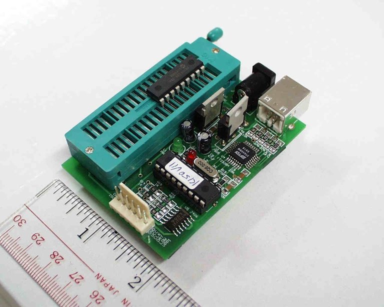
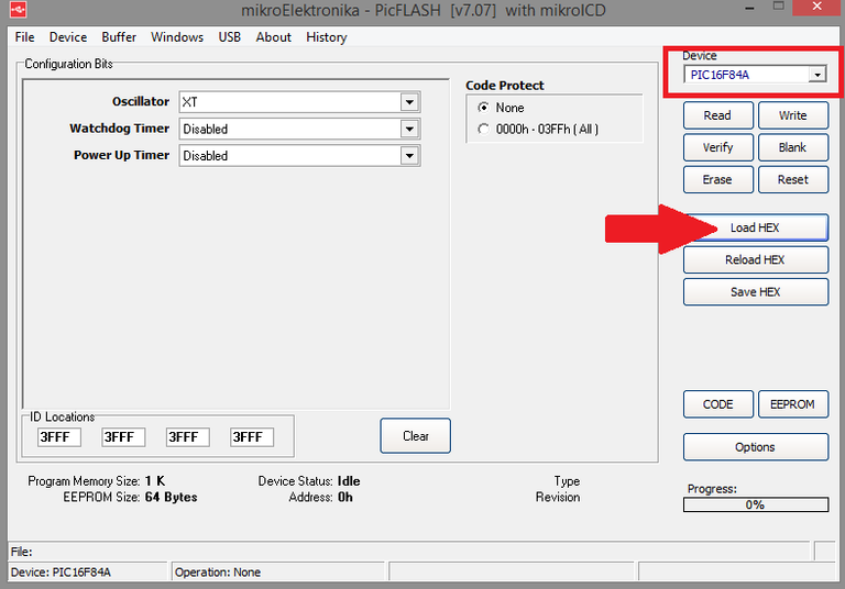
Click on "Write" and check the progess until it is 100% complete. Then, you have successfully programmed your microcontroller.
The PCB Masking and Assembly Process
Step 1: Print the PCB layout you acquired on the circuit modeling process. Clean the PCB with an abrasive material with care. Start the PCB masking process.
In this guide, I won't discuss the masking process since it has been required to have basic electronic skills to do this project. But, if you are new to the masking process, I recommend that you watch this online tutorial , first.

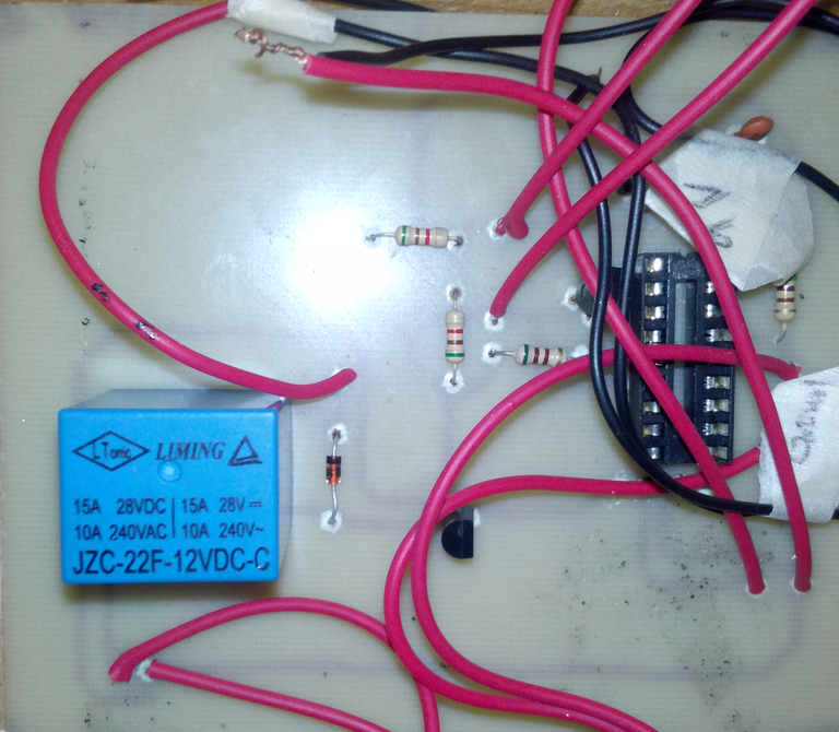
Step 2: Drill holes for the leads of the components on the PCB using the mini drill. Always refer to the circuit for a guide. When you are done, carefully place the components and solder them neatly and correctly. Don't forget to use the IC socket for the microcontroller.
Step 3: Testing your circuit. After connecting to the power supply, you can use a lighter or a hot soldering iron by placing it close to the the thermistor, to test if the buzzer sounds. If the buzzer sounds, you can reset the fire alarm by pressing the tact switch.
"Have you followed my guide? Do you have
questions?
I will be very happy to answer it on the comment section
below."
I will be very happy to answer it on the comment section below."
Mind blown! I am looking forward for more electronics engineering-related posts. And, I am also open for suggestions. More power to all Steemians!
Follow & Upvote
@japh
@japh
void main()
{
TRISB = 0X00;
TRISA = 0X1F;
PORTB = 0;
while (1)
{
if (PORTA==0X01)
{
while(1){
PORTB.F0 = 1;
}
}
else
PORTB = 0;
}
}
Nice post ! It is very detailed that I can make it a less than an hour haha ! Thank you ! It will be so helpful to students like me !
Wow! I am so happy that I have given a detailed instruction. I am trying my best to improve on my niche. Thank you @carpieew
oooh, so engineering and artsy, hehe, nice one bro! 👍😊❤️❤️❤️
Thank you @zephalexia. Your comment motivates me to post more like this.
This is a good project @japh. There are 2 programs involved and the level of making this out of hand amazes me. Keep it up!
Thank you @themanualbot. I have a vision for steemit. I hope that one day when engineering and technology students seek online resources. The top search will be here, in Steemit. I would like that to happen. I will continue my niche.
That's a very interesting project @japh! It is a great and cheap alternative for high end fire alarm system and also thank you for sharing the steps in how to make something like this, maybe I will try to make one for myself to avoid from getting burned alive. haha
I would recommend to use metal cases as a chassis for this project @ted7. Thank you so much!
Thanks for this step by step process @japh! With this Steemians can do their own fire alarm system by just following these easy steps. Keep it up buddy💯
Thank you so much my friend @dwaeji-aizelle! Yes, I really that the readers will also try to make this project.
This article is very helpful, voted to help writer continuing to post such articles.

I am very honored to hear that @vailantventures! Thanks!
This post has received a 0.09 % upvote from @drotto thanks to: @banjo.
This is very helpful, Thanks
I am glad that my blog is helping. I am very inspired now.
Very very impressive my friend. I just don't have the patience for such a project, but well done!
Thanks for the compliment, my friend. It motivates me to write more posts like this.
Impressive! A project worth reading. Thanks for sharing @japh. Incorporating your knowledge on both circuit design and microcontroller programming to make the project outstanding, the engineering way!
Really amazed me and blows me off.
The process takes some patience but the result is worth it. I am happy that I have used my niche to share my knowledge here in this platform.
My friend, great work! Follow you
Thanks for the appreciation @gleb-jeglov! I'm very happy to have a new friend here.
Hi @japh, your post was nominated for an upvote by @steemph.cebu for it's creative, thoughtful and impactful community content. Steem on friend :D
Thanks @sndbox and @steemph.cebu for the recognition of this post. I hope this post helps the community a lot especially in the areas of electronics and engineering. This design is a working prototype and I am eyeing for improvements in the future.