For part 1 of this 2 part series, a standard household Light Switch will be added to the ESP8266 microcontroller - using the Arduino IDE programming environment. After programming, uploading, and wiring the circuit for the switch the circuit for the switch, the switch will turn on and off the blue LED light that is on-board the ESP8266. Part 2 of the series will involve copying the switch code created in this part, and adding code to the previous project program that allowed control of a pair electrical outlets from a web page: Microcontrollers: Using ESP to Control Electrical Outlets from a Web Page
Why Add a Physical Switch ?
As fun and useful as it can be to turn things on and off from a web page, it's often easier to just flick a switch. My ultimate vision of a smart home is one that would have very few switches or web page controls - in a true smart home the switches work automatically with timers, motion sensors, temperature, other sensors - and other information - to save energy and time. Switches would also work as a nice backup if something happened to the router and the ESP8266 direct connect WiFi.
Arduino IDE - Adding a Button or Switch to the ESP
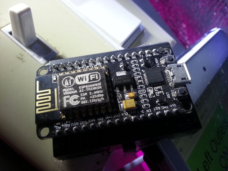
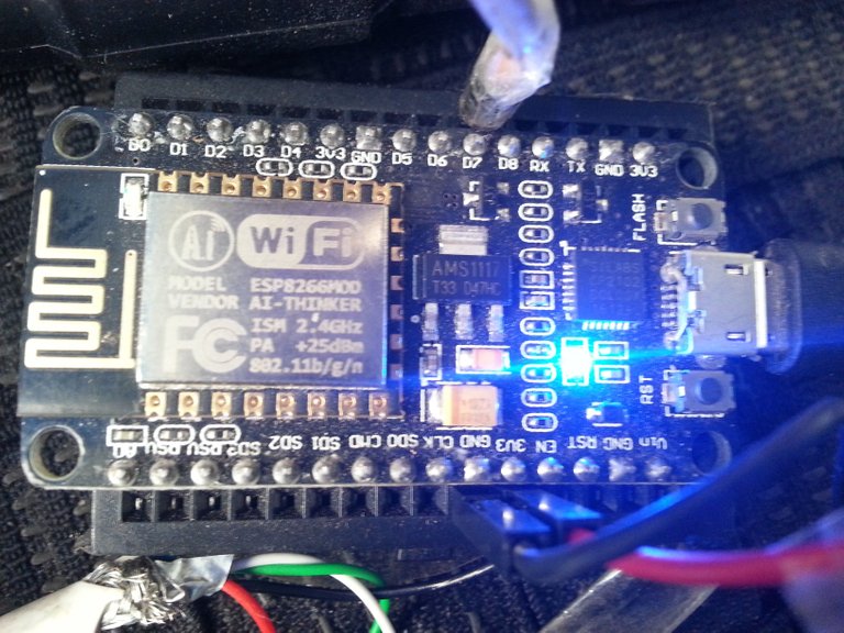
Buttons are essentially Switches that are turned on for only as long as the button is pushed. You can see the RST and FLASH buttons of the ESP8266 in the picture below. RST is Reset - when the RST button is pushed it restarts the ESP. The Flash button is used to put the ESP into upload mode where it is ready to receive a new program upload. The Flash button is usually not needed when uploading sketches or programs to the ESP with the Arduino IDE programming environment.

In the picture above you can also see the USB cable plugged into the ESP8266's on-board micro USB port. You can also see the on-board blue LED light. This blue LED light can be used for our own purposes.
Arduino IDE - Adding Sketch Notes or Documentation
In the Arduino IDE programming environment, any text on a line after the // is for notes or documentation and will be ignored by the compiler. If you would like to type multiple lines of text to be ignored by the compiler, then the notes or documentation can be started with /* and ended with an */ when the notation is finished.
Arduino IDE - The Button Sketch Example
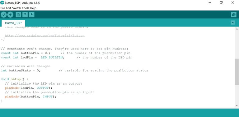
In the screen capture below you can see the button example code that comes with Arduino IDE. No libraries are required for this simple - digital input read - button sketch. Three variables are defined:
- buttonPin = D7; //D7 is the digital input pin on the ESP that will be used for the Light Switch.
- ledPin = LED_BUILTIN; // the compiler will substitute the correct digital pin for the built in LED light of the microcontroller board that was selected before compiling the sketch.
- buttonState = 0; // this variable is used to keep track of if a button is being pushed or released, or if a switch has been turned on or switched off.
In the screen capture above you can see the setup { } section. The mode of one of the microcontroller's digital i/o pins - pin number 'ledPin' - is being setup as an output pin. When the program compiles, the compiler will replace 'ledPin' with the value of that variable - in this case LED_BUILTIN which is explained above. If the programmer decided to use a different digital pin, it would be much easier in a large program to only have to change the digital pin number in one location - the variable definition section at the top of the program. Microcontroller output pins can be used to control micro-electronic items such as servos, LED lights, motor controllers, and relays that can turn any electrical item on or off. In the setup section you can also see another digital i/o pin being defined - this time as a digital input at the 'buttonPin' location. The 'buttonPin' variable was given a value of 'D7' in the variable declaration section at the top of the program.
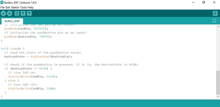
In the screen capture below you can see the loop { } section of this button program. The loop section repeats continuously while the program is being run by the microcontroller. First the 'buttonState' variable's value is being set equal to the value of the pin that the button or switch is connected to on the microcontroller. If the button is pressed or the switch is turned on then the value of the 'buttonPin' digital input read will be HIGH (one). If the switch is turned off or the button is released then the value of 'buttonState' will be set to LOW (zero).
In the loop section of the button program in the screen capture above, you can see the 'if...then...else' logic statement. In plain english this statement reads that if the button is being pressed, then the ledPin will be turned on (set to HIGH) - or else - If the button is not being pressed, then the ledPin will be turned of (set to LOW).
After compiling and uploading the button sketch to the ESP8266 microcontroller, next is the button circuit and wiring of the light switch. Below is an old video showing how to compile and upload a program to the ESP8266. If you would like more information about compiling and uploading a program, please visit Introduction to Microcontrollers for more information.
Standard Electrical Household Light Switch
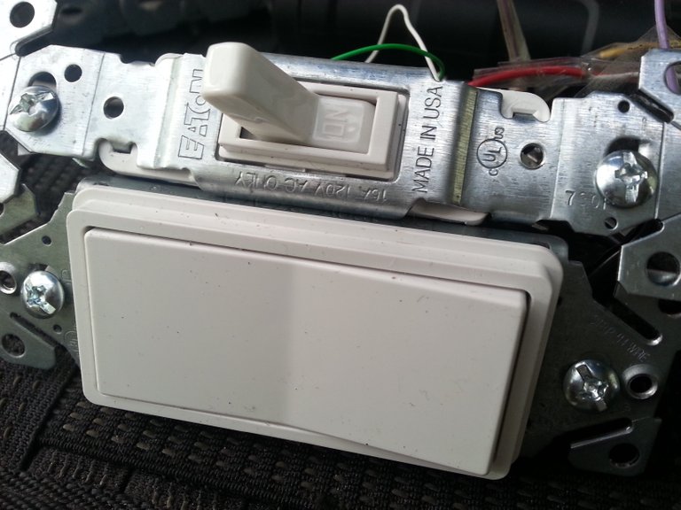
Usually this Light Switch is used for 120v alternating current electricity - It will also work well for a heavy duty 3 volt microcontroller switch. The light switch has two screw-down posts to hold the wires. If the switch is turned to the on position, then electricity can flow from one post to the next - through the switch. If the switch is turned to the off position, then electricity no longer can flow from post to post through the switch. A Light Switch is very similar to a button. A switch turned on would be the same as a holding the button pressed down. Releasing the button would be like turning the switch off.
Light Switch Wiring
To add light switch control to a microcontroller, the wiring and circuit is the same as for a button. To ultimately connect two switches, I am using an old USB cable. There are 4 wires in most USB cables - Red, Black, White, Green. Only two wires are required to send and receive from each switch. In the picture below you can see full wiring circuit setup for two switches. For this single light switch we will be using the white and green wires. On the left side of the picture below you can see the green and white wires each attached to one of the light switch posts. When the light switch is turned on, the electricity will flow through.
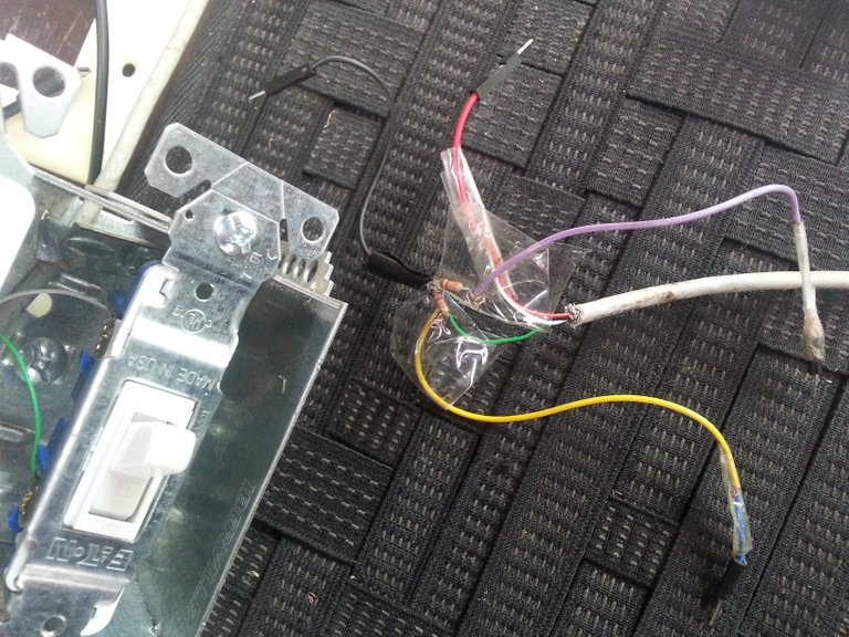
For easier connections to the microcontroller, the green wire is being used for black or direct current negative, the white wire is being used as red or direct current positive. With an attached breadboard jumper wire pin, the white wire or positive side will be connected to one of the 3 volt power supplies on the ESP8266 microcontroller board. The green wire splits with one wire going through a resistor connected to a black wire that goes to the microcontroller's ground pin. The other wire in the green split - the yellow wire - goes to the digital in pin of the microcontroller. When the light switch is turned on, the digital in pin will receive a HIGH signal. If the light switch is turned off, the digital in pin on the microcontroller will receive a LOW signal.
Why the Resistance? - Short Circuit Explanation
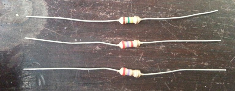
A 10K ohm resistor (Brown Black Orange Gold) is recommended for this button example sketch. The closest I had on hand was a 12K ohm resistor (Brown Red Orange Gold) - close enough, it will do. Without a resistor or other load on the circuit or wire between the positive and the negative connections, the wire or short circuit itself will become the resistance and the microcontroller the heat sink - both will become hot and use a lot of energy with nothing to slow it down. Adding the resistor slows the energy flow down a little. The ceramic resistors are used to slow the flow. When using LED lights resistors are needed or the LED light will become the resistor and burn bright and with a shortened life span.
Downloadable and Printable PDF file:
Connecting the Switch Circuit to the ESP Microcontroller
In the picture below you can see the pin from the yellow wire of the switch circuit plugged into the D7 microcontroller digital input on the breadboard. The Red wire from the circuit going to the 3V3 - one of the 3 volt outputs on the ESP. The black wire from the switch circuit is plugged into one of the GND microcontroller ground pins.
 =
=
Testing the Light Switch - Button Code using BUILTIN_LED
The video below is the testing of the light switch program and wired circuit. If the switched off the ESP onboard blue LED light turns on. When the light switch is switched off, the blue LED light turns off.
Now that the light switch is connected to the microcontroller - and the microcontroller has been programmed to know when it has been switched - Part 2 of this series will be to add this switch code or sketch to the previous electrical outlet control program from the previous microcontroller project: Microcontrollers: Using ESP to Control Electrical Outlets from a Web Page.
Arduino IDE button example:
https://www.arduino.cc/en/Tutorial/Button
Previous posts you may find interesting:
- Household Power Audit with the Kill-A-Watt Power Meter
- Get More Power out of your Off-Grid System with Single Voltage Conversion
- offgrid-online: My Solar Power Cabin Setup
Have a great day!
At first glance, this is so far outside my usual area of knowledge -- or interest, tbh, I thought WTF?? as I scrolled down the page. And I got totally lost. My fault. Not yours.
So then I said to myself, there must be something to this -- and scrolled back up to start over again and figure it out. And then lo, and behold, I realized what you're describing. Holy crap, that's amazing!!
When you get done with these posts, I want you to come up with something that cleans your house -- not just turns things on and off from a webpage. I don't dare let @catweasel see this. He never will get out of his computer chair. (What is it about computers? Why are they so mesmerizing? What have we done to ourselves?)
Now I'm serious about that cleaning deal. That and cooking. You come up with solutions to those issues, and you've got a real winner. I'll be watching for them. Don't think I won't.
Thanks @enchantedspirit - I appreciate you stopping by, and taking the time to read the post :) This one was a bit heavy on the programming side - but after I cover the basics, these microcontroller project posts will get a lot more interesting and practical. They may not get to the fully automated food cooking and house cleaning level, but they will be fun :)
Congratulations! This post has been chosen as one of the daily Whistle Stops for The STEEM Engine!
You can see your post's place along the track here: The Daily Whistle Stops, Issue #122 (5/2/18)
The STEEM Engine is an initiative dedicated to promoting meaningful engagement across Steemit. Find out more about us and join us today.