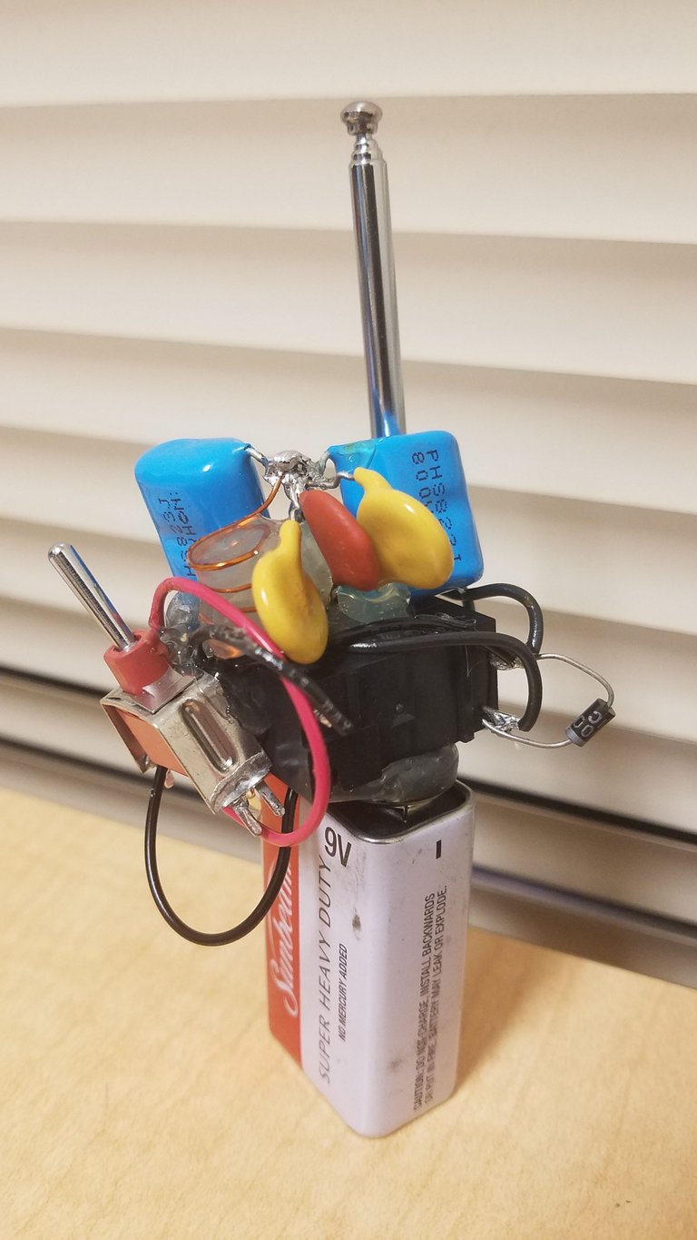
I had some time today to wrap up my relay radio transmitter. As expected (and hoped) it doesn't exactly produce enough signal to effectively cut out radios from more than a few feet away, but it does produce electromagnetic radiation (around 1 MHz in frequency). This frequency is within the AM band, so if you turn on this device next to an AM radio near 1 MHz the radio will cut out, playing only silence or slight static.

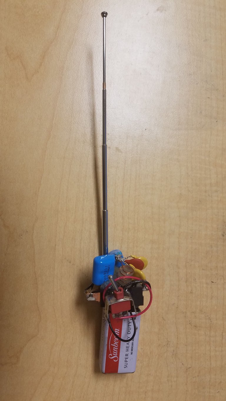
Yes, I know it's hideous. I didn't want to deal with perf board, but looking back I definitely should have.
This transmitter is essentially a mechanical spark-gap transmitter (see here for a real spark-gap transmitter demonstration). I got the idea to make one of these using a relay from an extremely brief video online, but ended up going my own route in terms of actually building/designing it. Note that intentionally jamming a signal is illegal in the United States. This device is simply meant to demonstrate the ability to generate electromagnetic radiation with a simple circuit made of salvaged parts. The area of detection for this transmitter is also way too small to actually affect anyone's ability to listen to the radio. I also operate it for only brief periods of time, making it much more of an electronics/physics demonstration than an actual useful "jammer".
What this device does is produce rapid pulses of 1 MHz EM radiation that can be picked up on properly tuned radio receivers. It's a really, really horrible transmitter: No ability to add in audio (yet?), radio waves only emitted in pulses, low power output, a terrible optimized antenna, and a low-reliability relay that rapidly clicks while in use. But: It does produce radio waves, so it sort of works. Note that it's not an AM transmitter since it can't transmit audio, it just operates on the AM band (around 1 MHz).
How it works
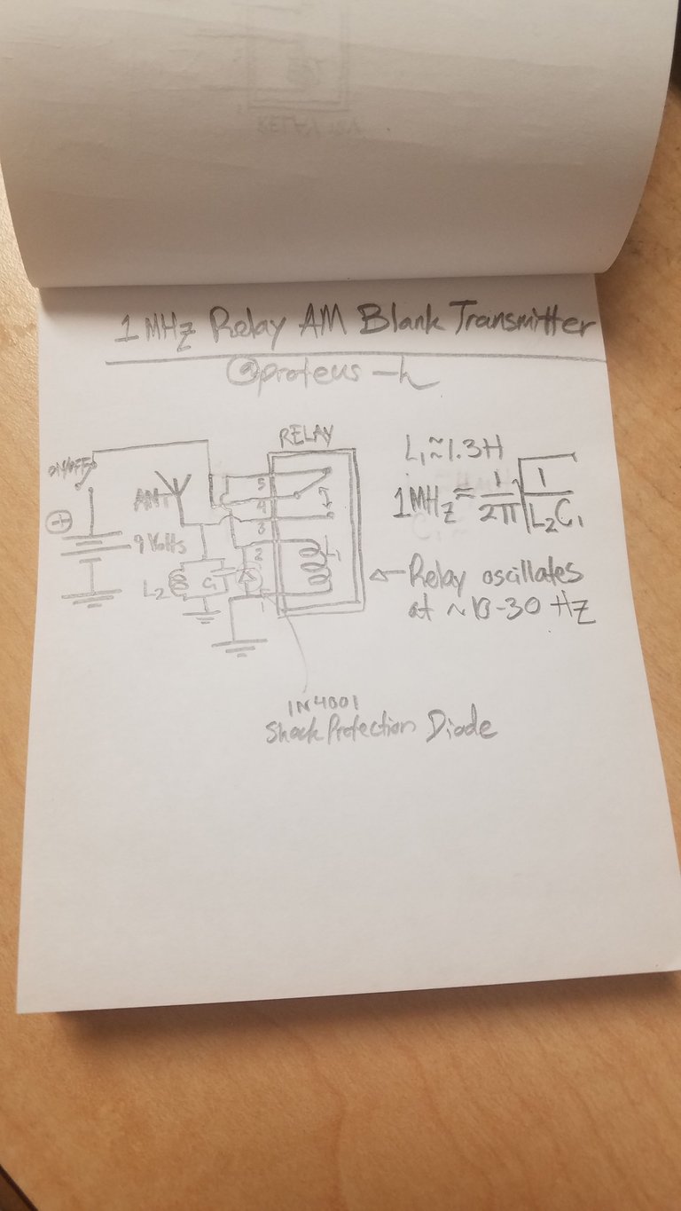
Here's a poorly drawn schematic I just drew. Note that semicircles over wires means that the wires don't connect.

Let's step through how it works.
The core of this device is a relay, salvaged from a microwave oven (actually, essentially every part of this device was salvaged from various trashed electronics). You can read more about how these work here. To summarize, this relay has a large coil of wire in side. If you run current through the coil, a big magnetic field is generated, pulling in a switch inside the relay. This disconnects the central pin from one of the outer pins, but connects it to the other outer pin. This lets a relay act as an electrical switch.
The circuit is powered by a 9 Volt battery that attaches to the bottom of the device. A metal switch controls the connection to the battery. Flip the switch and the device turns on.

The way I've wired the relay, current from the battery must flow through the switching part of the relay to get to the activation coil. So when you flip the switch, current does just that. It goes through two of the switching pins down through the large inductor coil inside the relay. This magnetically pulls down the switch, connecting pins 3 and 4 and disconnecting pins 4 and 5. But the connection between the battery and the coil went through the switch, so once the switch is pulled down by the magnetic coil, power to the coil itself is cut off.
Since the coil is an inductor, cutting off the current causes a large voltage spike across the coil. This is actually enough to shock me (as I learned while testing the first iteration of this), so I added in a diode across the coil. Current from the battery can't pass through the diode, but when the coil fires up its voltage spike (after the battery disconnects), the diode discharges the inductor, limiting the output voltage to less than a volt and preventing any annoying shocks.
Once the coil turns off (due to the lack of power), the switch once again falls back to its original position, re-powering the coil. The result is that the relay rapidly turns on and off (at least 10 times a second), resulting in a loud clicking noise when you turn on the device. This is sure to cause problems eventually due to wear and tear on the relay, but this relay has been sitting in my junk parts box for a year now, so I don't really care.
I have connected an inductor and capacitor in parallel running from pin 3 to ground. Well, 6 capacitors to be exact. This circuit acts as the actual radio-frequency oscillator. When the coil pulls the switch down via magnetism, battery current can now flow directly through the inductor-capacitor portion, and most likely primarily flows through the inductor L2. L2 is a very small inductor, produced by me winding 4 or 5 turns of copper wire around a pencil.
This LC pair will oscillate at a given frequency, passing charge between the two elements until leftover resistance in the wires causes the oscillation to die out. The exact frequency is determined by the inductance and capacitance of the inductor and capacitor, and is given by:
f = (1/2pi) * sqrt(1/(L*C))
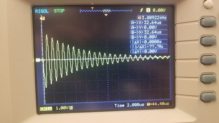
My original estimate of the tiny wire coil's inductance led me to put a 3 nanofarad capacitor from my salvaged parts bin into the transmitter part of the circuit. Using an oscilloscope from a lab I'm part of on campus, I discovered that the circuit was oscillating at a frequency of around 9 MHz - way too high to be detectable on an AM radio set that only goes up to 1.7 MHz. Due to some math errors and not having exact capacitor values, I ended up with 6 capacitors in parallel to add the capacitances across the inductor.

Image of LC oscillation at ~1 MHz on campus oscilloscope. You can see that the oscillation dies out over time. I measured the period of the waves in order to figure out the frequency.
The result is that the LC circuit oscillates at right around 1 MHz - perfect to hear on my AM radio. This oscillation is caused by the inductor and capacitor charging and discharging each other many times over. Every time the relay switch restarts, the LC circuit gets a boost of power, which is then thrown back and forth between the capacitors and the inductor until energy is lost to heating and EM waves.
I attached one of the crappy extending antennas from the awful 50 MHz walkie talkies I got on Ebay a few weeks ago. Somehow this circuit managed to be slightly less useful than those terrible radios. This antenna is way too short to be resonant at 1 MHz, but it'll do, and being totally un-optimized it won't broadcast the signal too far and mess with other people's radios. As you can see, my general lack of radio theory knowledge comes in handy when it comes to legal stuff!
The antenna lets these oscillations lose energy by radiating out electromagnetic waves into the environment. I don't have a way to measure the output power, but it's low.
If I tune my AM radio set to a station around 1 MHz, turning on the relay transmitter will totally silence the station (with some static - you can actually hear the relay in the radio set ...) out to about a meter at best. Like I said, this isn't exactly the world's most useful device.
I'm still pretty happy with this little device since I made it almost entirely out of scrap parts (I think the battery clip and wires were the only things I didn't get out of old electronics) and it does actually radiate some radio waves that I can detect. I'm curious if there's a way to transmit audio with this circuit, especially since I can actually hear what appear to be the clicks of the relay across the air in my AM receiver.
I hope you found this writeup on me learning about basic RF somewhat interesting. I still have the vast majority of information about radio to learn, so I will probably be able to build a better device somewhat soon. I'll try my best to answer any questions you may have.
- And remember, don't build an actual jammer that can block signals at a distance (this one barely works at 3 feet), as this is likely quite illegal in your country.
Thanks for reading!
All images used in this post are my own. You are welcome to use them with credit.
Being A SteemStem Member
Totally ugly, but we do not ask it to be beautiful ^^
Cool little project. Might be interesting to try to make a circuit that could broadcast actual noise on multiple frequencies within a certain distance. That way, it could play to multiple stations on a radio it was next to. :D
Not sure how legal it would be though...probably not at all...
Such a circuit would want a transistor and not a relay :) I hope to build some more transmitters in the future and get to the point where they are actually useful.
And hopefully look a bit better. :P
Wow, you did what you said. I will read completely and edit this comment. Congratulations...
Now I have seen a battery with an attatched (and somewhat functional) antenna. Congratulations! This is a work of art ...
Art is definitely not what I'd call it, but I'm glad you enjoyed it! What it lacks for in looks it makes up for in how interesting it was to build and test.
Haha, awesome work man! Reminds me of something out of a cartoon :)
This is a small project. And its model is very good. I would say it is very good.
Congratulation for making it right . range doesn't matter , you can make it more efficient when u make it further work on it. but its looking complected when i see the pic , parts are well into each other.
Yeah I like that dude, when it worked I bet you were well happy. Good job!