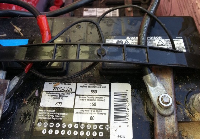
I produce my own electricity with solar panels during the day. Excess electricity is stored in 12 volt lead acid batteries for night time and cloudy day use. I use a backup gas generator to charge up the batteries if there hasn't been enough sunshine. As electricity is used from lead acid batteries, the voltage reading from the batteries gets lower and lower. A sealed 12 volt lead acid battery will read 12.7 volts when 100% fully charged, and 11.8 volts when empty.
Micro-controller for Wireless Voltage Reading
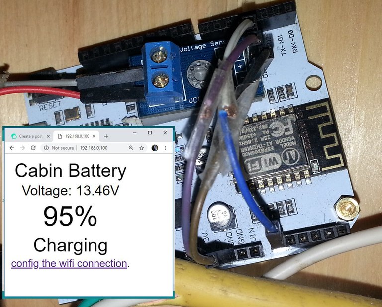
Most solar charge controllers and inverters will tell you the battery voltage, but I wanted to make the battery voltage easily accessible for quick reference, data collection, and automation potential. I'm using a $10 USD programmable ESP8266 WiFi micro-controller with a voltage sensor to serve a local web page that is easily accessible from a web browser on my phone, tablet, or PC.
|
|
ESP8266 WiFi Micro-Controller
In previous project I used digital inputs and outputs on a ESP8266 to turn household electrical outlets on and off with switches - or from a web page. For more detailed information about that project and micro-controllers, these previous posts may be useful:
- Microcontroller: Using ESP to Control Electrical Outlets from a Web Page
- Microcontroller: Programming and Wiring a Switch Circuit for ESP - Part 1
- Microcontroller: Switches and a Web Page to Control Electrical Outlets - Part 2
ESP8266 Analog Sensor Input
Along with digital inputs and outputs, ESP8266 micro-controllers have one analog input (A0). You can see the A0 pin on the left side - at the bottom of the LinkNode D1 board in the picture below. Analog inputs can read a range of values derived from the incoming voltage. ESP8266 analog inputs read a range of voltage values anywhere from 0v to 1v. The analog voltage sensor I am using for the project takes the 0v to 25v reading from the battery and condenses that to the 0v to 1v range to send to the micro-controller. By comparison, classic Arduino micro-controller analog inputs can read 0v-5v ranges. 5v analog readings would be more precise, but for my cabin battery voltage reading purposes, precision is not necessary.
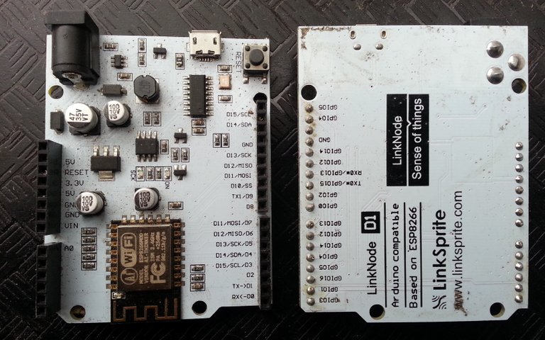
This LinkNode D1 ESP8266 is powered and programmed with a 5 volt micro USB. It can also be powered with 5 volts from the VIN and GND pins - or with 9-24 volts using the barrel jack. The voltages are converted down to the 3.3v that the micro-controller uses, but are available from the VIN and 5v pins for other attachments like displays or motor controllers that may require 5v or more.
Voltage Sensor
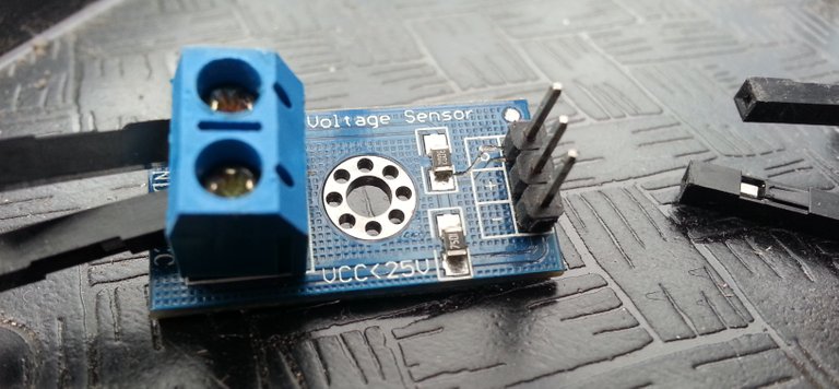
In the picture below you can see the small $6 USD voltage sensor. On the left side are the screw terminals for the positive and negative wires that connect to the batteries for voltage reading. On the right side you can see the wire jumper pins for connecting to the micro-controller - Signal, Positive (3.3v), and Negative pins.
Voltage Sensor Example Sketch
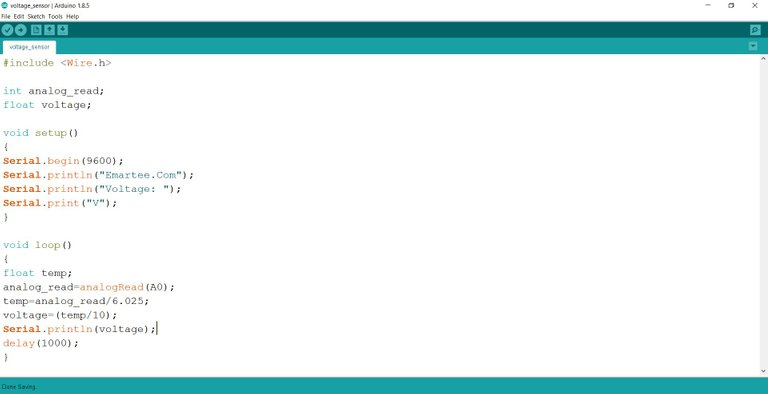
In the screen capture below you can see the voltage sensor example sketch/program in the Arduino programming environment that I use to program the ESP8266. A very simple sketch that includes an Arduino Wire library used to read the voltage value from the analog input. The sketch setup prepares the serial port for data monitoring. The looping part of the program reads the analog input, does some basic calculations to convert back to the proper voltage, prints the voltage to a line on the serial monitor, and pauses for one second (1000ms) - then repeats the loop.
Voltage Sensor Example Sketch from Emartee.Com
Adding the Voltage Sensor
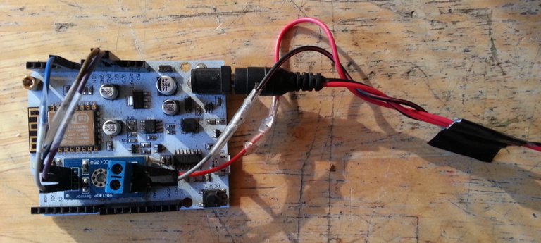
In the picture below you can see the LinkNode with the voltage sensor attached with double-sided foam tape. Wire jumpers have been shortened to make tidy connections from the signal pin on the sensor to the A0 analog input pin on the LinkNode, from the - on the sensor to the GND on the LinkNode, and from the + pin on the sensor to the 3.3v pin on the LinkNode. I'm using the barrel jack to power the LinkNode from the cabin batteries. The battery input wires from the screw terminals on the voltage sensor have been spliced into the barrel jack wire that is going to the cabin batteries for reading the voltage.
Core ESP8266 Sketch
The core sketch I like to use for ESP8266 micro-controllers is the ESP Advanced Portal sketch. It creates a WiFi portal that you can connect to with your phone, tablet, or PC. While connected you can go to the 192.168.4.1 local page to view the data from the served web page. From the portal web page you can also connect the ESP8266 to your WiFi router for easy access after reconnecting to your WiFi router.
Combining the Code
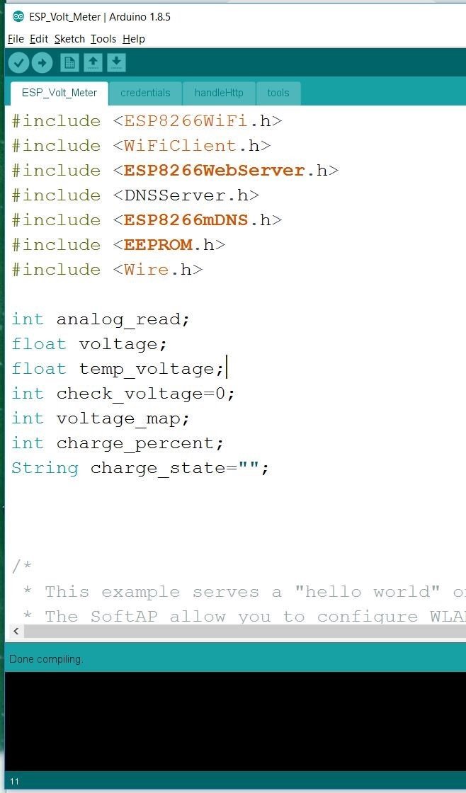
In the first screen capture below you can see the ESP Advanced Portal sketch with many library includes for it's WiFi handling. You can also see that I've added the #include <Wire.h> from the voltage sensor sketch for reading the analog input. I've also added a few additional variables including integer (int) variables for whole numbers, string (String) variables for text and words to be displayed, and floating (float) variables for numbers that have decimal places.
|

|
In the second screen capture above, you can see the setup section of the ESP Advanced Portal with the not required Serial.prints added from the voltage sensor example sketch. The Serial.begin(9600) line starts the serial communication at 9600 baud rate - I'll be using the served web page to view sensor information.
The Main Loop
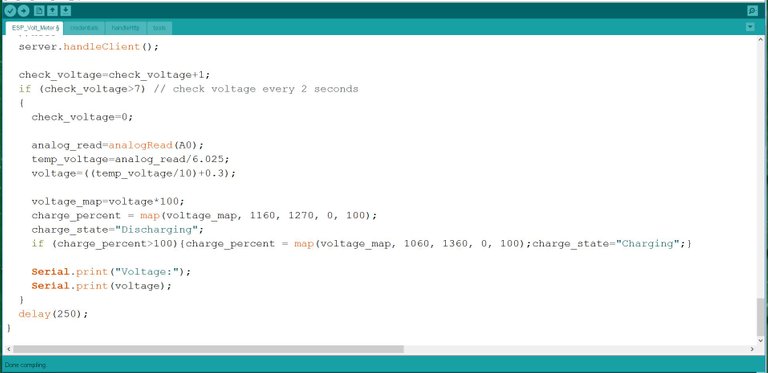
The Loop in the Arduino programming environment is the part of the program that repeats continuously. In the screen capture below you can see the voltage sensor code that was added to the end of the ESP Advanced Portal loop. The ESP8266 micro-controllers run through the loop section once every millisecond - or 1000 times per second. Reading the voltage sensor 1000 times per second is unnecessary and a waste of power. You can see the delay(250); at the end of the loop - this pauses the loop for 250 milliseconds so that the loop is only ran 4 times per second. The check_voltage variable value is increased by 1 each time the loop is ran. If the loop ran 4 times, that would be 1 second, so every 8 runs (2 seconds) the voltage sensor is checked. Checking every 2 seconds is probably still far too often for my needs, I will eventually increase the time between checking.
Battery Discharging
In the screen capture above you can see where the 11.60-12.70 voltage is mapped to 0-100. If the voltage read is 11.6 volts, then the charge percent would be set to 0%, 12.7 volts would set the charge percent to 100%, and every value inbetween. Sealed lead acid batteries are considered empty at 11.8 volts, but I usually have at least a 0.2 volt load on the batteries that causes it to read 0.2 lower than actual voltage. A sealed lead acid battery is considered full at 12.7 volts, I will eventually change the mapping 1270 to 1250 to reflect the usual 0.2 volt load.
Battery Charging
To charge 12 volt batteries, solar charge and battery charge controllers send 14.3 volts to the battery. While charging the read voltage will be around 1.5 volts higher because it is combining the 14.3 volts from the charger with the current charge voltage of the 12 volt batteries. This is why the if-then statement was added. If the batteries are charging and the charge percent goes over the 12.7 volt 100%, then the charge percent is re-mapped with the new 13.6 volt (1360) value set at 100%. I'll be changing this to 1430 to reflect the true 100% and charging value of 14.3 volts. The charge_state string variable is also changed to "Charging" from "Discharging" if the voltage goes above 12.7 volts. This string will be used to display on the served web page.
- Voltage Reference: Energy Matters: Deep Cycle Battery Voltage & State of Charge
Uploading the Sketch to the Micro-controller
In the picture below you can see I've prepared for uploading from the Arduino PE on the PC to the micro-controller. I've unplugged the barrel jack and the sensor pins, and connected the micro USB from the micro-controller to the tablet.
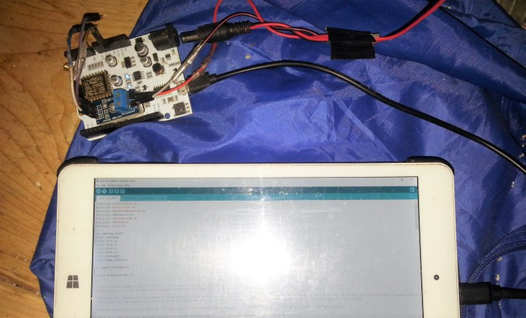
After selecting the Com 4 port the PC assigned to the micro-controller, the sketch/program was compiled, then uploaded.
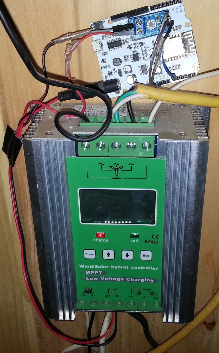
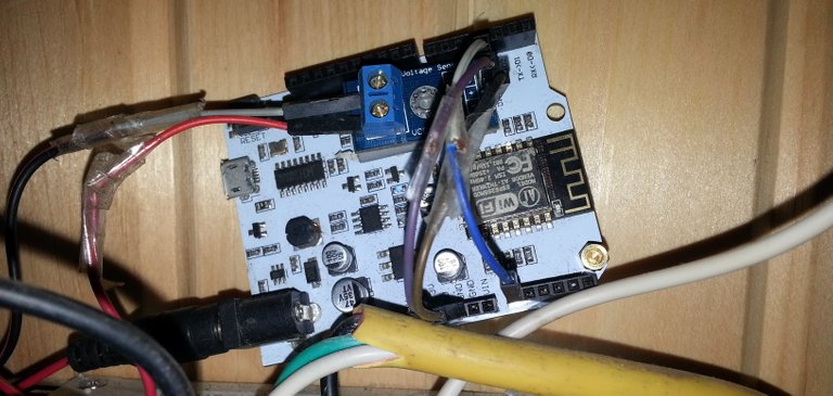
After the sketch was uploaded to the micro-controller, the jumper wires going from the voltage sensor to the micro-controller were re-attached and the barrel jack re-inserted to power the device. In the picture below you can see that the battery wires going into one of the charge controllers was an easy place for me to attach the + and - wires going to the barrel jack and voltage sensor. For now I've tucked the small device above the charge controller - I will eventually find case to properly mount it.
|
|
Info Display on the Micro-controller Web Page
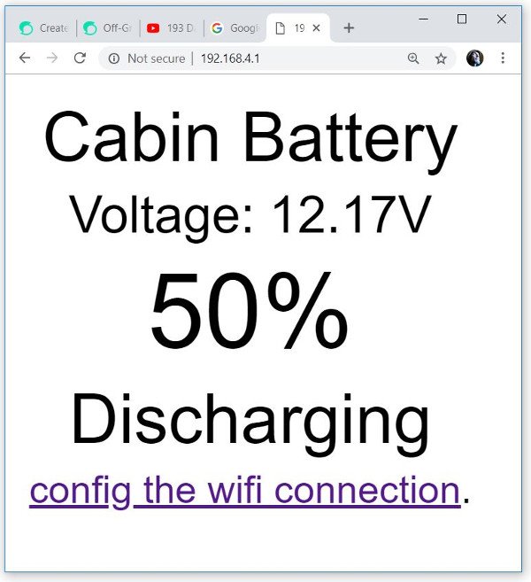
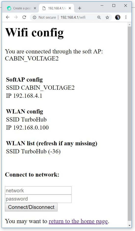
After a few seconds the device boots up for the first time. I go to my WiFi connections and connect to the CABIN_VOLTAGE connection. In the first picture below you can see the screen capture of the web page that appears when I go to http://192.168.4.1 in my web browser. After clicking the "config the wifi connection." link, the web page served from the device is shown in the second screen capture below. From this "WiFi Config" page the device can be connected to your local router for easy access. You can see that I have already connected to my TurboHub. When on the TurboHub router as per usual, I can access the Voltage Sensor web page with the http://192.168.0.100 address.
|
|

|
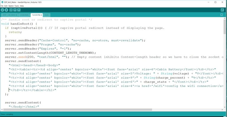
In the screen captures above you can see how the device serves a web page containing voltage and battery charge information. In the screen capture below you can see the HTML code on the "HandleHttp" page of the ESP_Volt_Meter sketch. The displayed web page can be customized as much as you like including text changing color depending on it's value - 100% being green and 0% being in red for example.
Upgrades to Do
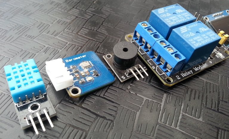
Many more sensors, programming, and electronics can be added to this project to make it do more. I will soon be adding a temperature and humidity sensor for the cabin to add to the web page display. Relays can be added to turn off electrical outlets if the battery voltage is getting low, or to turn on outlets for fans or boilers to use excess electricity when the battery voltage is high. A beeper can be added to beep when voltage is getting low or high. It would be easy to create a thermostat to control greenhouse ventilation, or check ground moisture to control irrigation. Micro-controllers can be useful to automate many tasks.
Project Files:
- ESP Advanced Portal from the GitHub DNSServer ESP8266 Library
- Voltage Sensor Example Sketch from Emartee.Com
- Completed ESP_Volt_Meter sketch files ZIPPED.

Hi jackdub,
Visit curiesteem.com or join the Curie Discord community to learn more.
Many thanks @curie! You all are awesome :)
This is amazing @jackdub ive been working on something similar with a wemos d1 mini pro those little esp8266 are great so many ideas to implement but not enough time haha. Im going to bookmark this to come back to great write up 👍
Posted using Partiko Android
A lot of potential control with these little micro-controllers - if I don't have an exact project in mind I could lose months fiddling :) They take a little more electricity and are a bit pricier, but the raspberry pi boards can be fun, and great for a network of homemade things hub :)
Yeah love the raspberry pi boards got about 5 haha... coukd be time to dust the spares off and start a new project just ordered one of those voltage sensors to add what you did into my green house 😀
Posted using Partiko Android
Congratulations! This post has been chosen as one of the daily Whistle Stops for The STEEM Engine!
You can see your post's place along the track here: The Daily Whistle Stops, Issue 324 (11/27/18)
Thanks @thesteemengine - I enjoy the community :)
Being a comms tech back in the day I can relate to this project, thanks for such an interesting post
Thanks - when you know what to look for, little micro-controllers are everywhere :)
Ohh yes that’s ndeed I have a few of different types in a drawer at work
Wow this is awesome post. So much info and details. Great content @jackdub.
Thanks, these little micro-controllers are fun to play with, and to put to good use. They're nice to look at too, i've spent much time admiring their shiny parts :)
You must be very techie @jackdub. You need to have knowledge on programming to control the micro-board. Are you a programmer in micro chips company? It seems not easy to do for people who have no knowledge in programming.
What brought you the idea to develop one yourself? An interesting post and it brought a lot of information to people who loves innovation.
This is very interesting. My cousin makes his electricity himself using the solar panels as well and I know that he struggled to collect the data that he wanted. I'll show him your post as he is a programmer so should manage to set it up. I think he was just missing the required idea :)
Thank you for sharing!
¡Te felicito @jackdub! por crear, tu propia electricidad, eso es lo que tendremos, que hacer muchos venezolanos, ya que constantemente, se va la luz, no es nada fácil hacer eso, ¿En cuánto tiempo hiciste el proyecto? ¿Vives en un lugar apartado del servicio eléctrico? o ¿El servicio es muy caro? ¿Cuál fue tu motivación, para desarrollar este proyecto? jajaja disculpa, tantas preguntas, pero me falta la última ¿cómo te sentiste con tu voto Curie? Un abrazo cariñoso.
holy sh.... you are unbiliebeve dude. how much money you spend on that project?
This is really great @jackdub! It sure opens a lot of possibilities for automation!
Thanks - it can tell time too, so that opens the door to scheduled events too - many possibilities :)
Yeah @jackdub that really makes a great foundation for an automation system. A few things that I have thought of since reading that article are:
The use of sensors for water pressure (and water flow) to automate water flow/drainage/pumping in any type of water system.
The use of temperature sensors to power on and power off fans, Peltier devices or other cooling systems for electronics.
The use of a miniature weather station to gather statistical data about the sun, wind and rainfall.
The use of something like Serval Mesh to power on when there is no internet or cellular connection. This would make it possible for everyone within range to use their phones to communicate with each other without the need for outside cellular towers or household WiFi. Further reading: http://developer.servalproject.org/dokuwiki/doku.php
The use of door and cabinet door sensors that turn on/off lights when they are opened or closed. This could be further controlled by time constraints as well so as an example: the porch light only comes on at night when the porch door is open.
I will probably think of more. :)